
High-voltage-dropout-type fuse cutout

A drop-out fuse and high-voltage technology, applied in the field of fuses and high-voltage drop-out fuses, can solve problems such as arc extinguishing cover damage, achieve reliable arc extinguishing, prolong service life, and strengthen arc extinguishing ability.

Inactive Publication Date: 2012-02-08
SUZHOUSNLIAN HIGH TENSION CONDENSER
View PDF5 Cites 6 Cited by
  • Summary
  • Abstract
  • Description
  • Claims
  • Application Information

AI Technical Summary

Problems solved by technology

[0002] At present, my country's power system generally uses overhead insulated lines in urban distribution networks, and its usage accounts for more than 70% of the distribution network. High-voltage drop-out fuses are widely used in overhead insulated lines to break the load current of electrical equipment and Provide overload protection for electrical equipment; and the existing high-voltage drop-out fuses include melting tubes, fuses, static contacts, static contact brackets, post insulators, moving contacts, moving contact brackets, and arc extinguishing covers; The static contact is set on the melting tube, the static contact bracket is set on one end of the post insulator; the moving contact is set on the other end of the post insulator; the moving contact bracket is set on the melting tube; The moving contact is also provided with an arc extinguishing cover; the fuse tightens the moving contact on the moving contact bracket, and the static contact bracket and the moving contact are provided with wiring bolts; when the fuse is blown, it will An arc is generated, and the arc is ejected from the capacitor tube and sprayed onto the arc extinguishing cover. Usually, once an arc is generated, the arc extinguishing cover will be damaged, and the arc extinguishing cover needs to be replaced when the circuit is repaired.

Method used


Image

  • High-voltage-dropout-type fuse cutout
  • High-voltage-dropout-type fuse cutout
  • High-voltage-dropout-type fuse cutout

Examples


Embodiment Construction

[0013] The present invention is described below in conjunction with accompanying drawing.

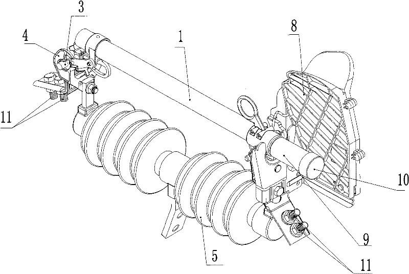
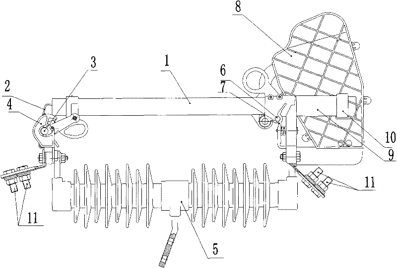
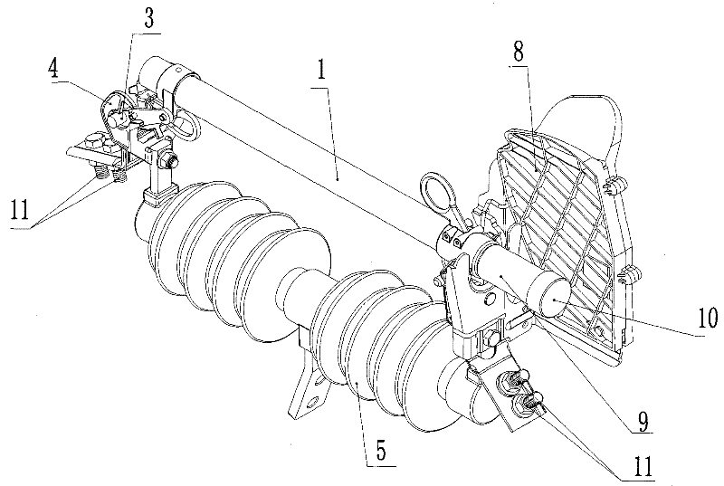
[0014] as attached figure 1 , 2 Shown is a high-voltage drop-out fuse of the present invention, including a melting tube 1, a fuse 2, a static contact 3, a static contact bracket 4, a post insulator 5, a moving contact 6, a moving contact bracket 7, a Arc cover 8; the static contact 3 is arranged on the melting tube 1, the static contact bracket 4 is arranged on one end of the post insulator 5; the moving contact 6 is arranged on the other end of the post insulator 5; the moving contact The contact bracket 7 is set on the melting tube 1; the moving contact 6 is also provided with an arc extinguishing cover 8; the fuse 2 tightens the moving contact 6 on the moving contact bracket 7, and the static contact The head bracket 4 and the moving contact 6 are provided with wiring bolts 11; the end of the moving contact bracket of the melting tube 1 is also provided with a diversion tube 9, an...


PUM


Abstract

The invention discloses a high-voltage-dropout-type fuse cutout comprising a fuse tube, a fuse wire, a fixed contact, a fixed contact support, a pillar insulator, a moving contact, a moving contact support and an arcing shield, wherein the fixed contact is arranged on the fuse tube; the fixed contact support is arranged at one end of the pillar insulator; the moving contact is arranged at the other end of the pillar insulator; the moving contact support is arranged on the fuse tube; the moving contact is also provided with the arcing shield; the fuse wire is used for tensioning the moving contact on the moving contact support; the fixed contact support and the moving contact are provided with a wire connecting bolt respectively; and the moving contact support end of the fuse tube is also provided with a flow guide tube, and one end of the flow guide tube is provided with a cover. Because the flow guide tube and the cover used for covering the end of the flow guide tube are arranged at one side of the arcing shield of the fuse tube in the scheme, the damages to the arcing shield caused by arcs can be reduced, thus the arcing shield can be repeatedly used.

Description

technical field [0001] The invention relates to a fuse, in particular to a high-voltage drop-out fuse capable of reducing arc hazards, and belongs to the technical field of electrical equipment. Background technique [0002] At present, my country's power system generally uses overhead insulated lines in urban distribution networks, and its usage accounts for more than 70% of the distribution network. High-voltage drop-out fuses are widely used in overhead insulated lines to break the load current of electrical equipment and Provide overload protection for electrical equipment; and the existing high-voltage drop-out fuses include melting tubes, fuses, static contacts, static contact brackets, post insulators, moving contacts, moving contact brackets, and arc extinguishing covers; The static contact is arranged on the melting tube, and the static contact bracket is arranged on one end of the post insulator; the moving contact is arranged on the other end of the post insulator; ...

Claims


Application Information

Patent Timeline
Patent Type & Authority Applications(China)
IPC IPC(8): H01H85/54H01H71/20
Inventor 查阿六
Owner SUZHOUSNLIAN HIGH TENSION CONDENSER
Learn More