

Wireless energy transmission device
A wireless energy transmission and transmitting device technology, applied in circuit devices, electrical components, electromagnetic wave systems, etc., can solve the problems of difficulty in manufacturing and use, affecting transmission efficiency, etc., to achieve high transmission efficiency, good transmission efficiency, and suitable for batch manufacturing and promotion effect
- Summary
- Abstract
- Description
- Claims
- Application Information
AI Technical Summary
Problems solved by technology
Method used
Image

Examples
Embodiment 1
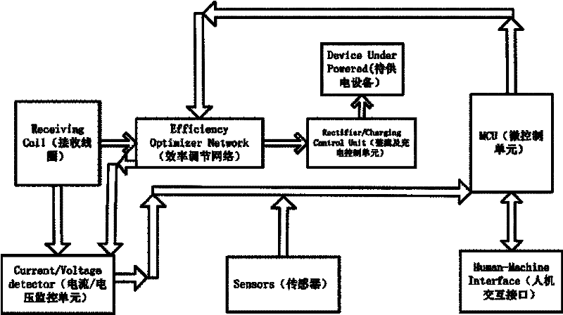
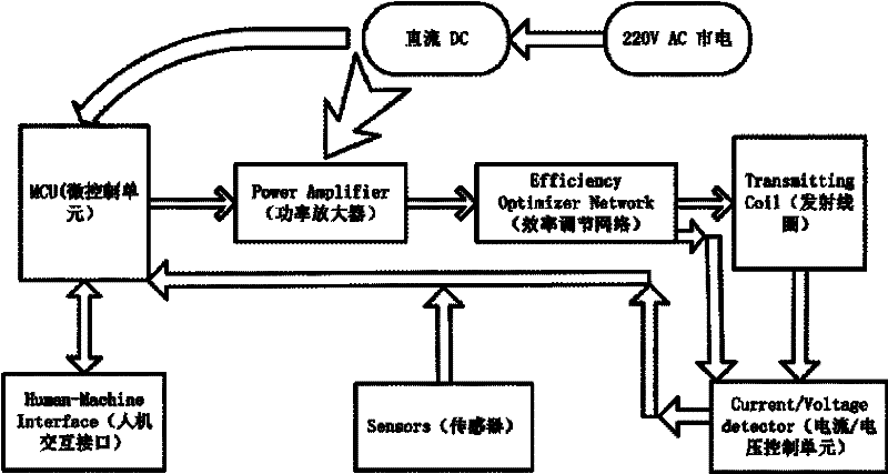
[0081] see figure 1 , the present invention includes a power source 1 , a transmitting device, a receiving device and a receiving load 6 . In this embodiment, the receiving load 6 can be a device to be powered and / or a charging device, such as a pure resistance or a reactive component, a device that directly consumes power such as a light bulb, or a device with stored energy such as a battery, or While consuming and storing, such as a computer or mobile phone with a rechargeable battery; the power source 1 uses a radio frequency power supply.
[0082] Wherein, the transmitting device includes a transmitting coil 3 and an efficiency-adjusting transmitting network 2 , the transmitting coil 3 is connected to the Port2 port of the efficiency-adjusting transmitting network 2 , and the power source 1 is connected to the Port1 port of the efficiency-adjusting transmitting network 2 .
[0083] The receiving device includes a receiving coil 4 and an efficiency adjusting receiving netw...
Embodiment 2
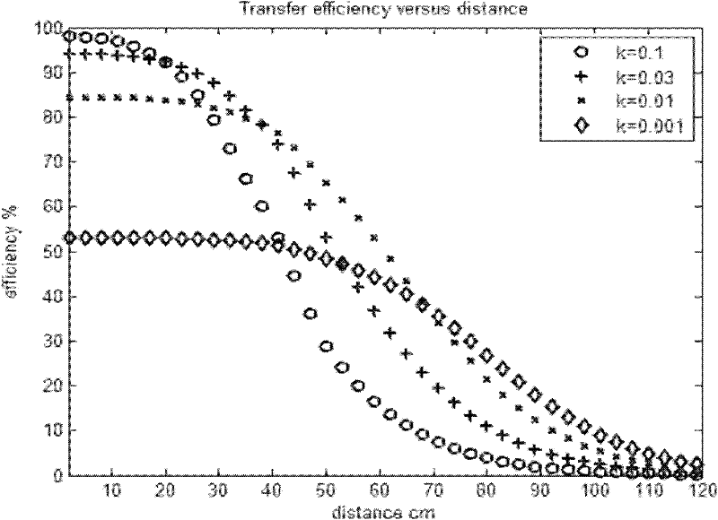
[0186] In Embodiment 1, the transmitting coil 3 and the receiving coil 4 are equal. In order to illustrate that the entire wireless energy transmission network is also applicable to asymmetrical situations, in this embodiment, the transmitting coil 3 and the receiving coil 4 are not equal in size.
[0187] The specific circuit parameters are: L t = 16μH, Lr = 1.4μH, R pt = 1ohm, R pr = 0.2ohm, R L =100ohm, R s =26ohm, k=0.05, f=4Mhz.
[0188] According to the above formula, C1=71pF, C2=28pF, C3=946pF, C4=184pF. Through numerical simulation, the relationship between efficiency and coupling coefficient k can be obtained, such as Figure 33 As shown, it can be seen that when k=0.05, the transmission efficiency reaches 85.24%. As the distance increases, k increases, and the transmission efficiency further improves. When k=0.3, it reaches 91.85%. In addition, it can be seen that when k When >0.01, the transmission efficiency is always greater than 30%.
[0189] The present i...
Embodiment 3
[0191] Example 1, R eqr > R L and R eqt s , the efficiency adjustment receiving network 5 adopts a CL2 type efficiency adjustment network, the efficiency adjustment transmission network 2 adopts an AL1 type efficiency adjustment network, and the entire wireless energy transmission device works in states A-C.
[0192] see Figure 35 As shown, there is a power source 1, the power source optimal load resistance R s = 50 ohms, receiving load R L =0.5 ohm, the present invention sets operating frequency as f=10MHz, then the best equivalent receiving impedance Z of efficiency can be obtained according to the method provided by the present invention eqr and the best efficiency equivalent emission impedance Z eqt , and according to the efficiency formula provided by the present invention, the estimated maximum efficiency is 81.79%, and the specific parameters are as shown in Table 2,
[0193]
[0194] Table 2
[0195] In order to achieve maximum efficiency transmission, the ...
PUM
 Abstract
Description
Claims
Application Information