Inverter device

An inverter and fuse technology, applied in the field of general inverter devices, can solve the problems of increasing the horizontal width of the substrate 1, increasing the interval D, etc.

Inactive Publication Date: 2012-02-08
FUJI ELECTRIC CO LTD
View PDF4 Cites 4 Cited by
  • Summary
  • Abstract
  • Description
  • Claims
  • Application Information

AI Technical Summary

Problems solved by technology

However, if attention is paid to the wiring path of the bus bars, since the bus bars 7R and 7T connecting the secondary-side terminals of the electromagnetic contactor 4 and the terminals (lower side) of the fuse 5 are bent in an S shape, an insulation distance (spatial distance) is included. ) between the electromagnetic contactor 4 and the fuse 5 and input CT 6 provided on the side of the electromagnetic contactor 4 increases, and thus the required horizontal width dimension of the substrate 1 increases

Method used


Image

  • Inverter device
  • Inverter device
  • Inverter device

Examples


Embodiment Construction

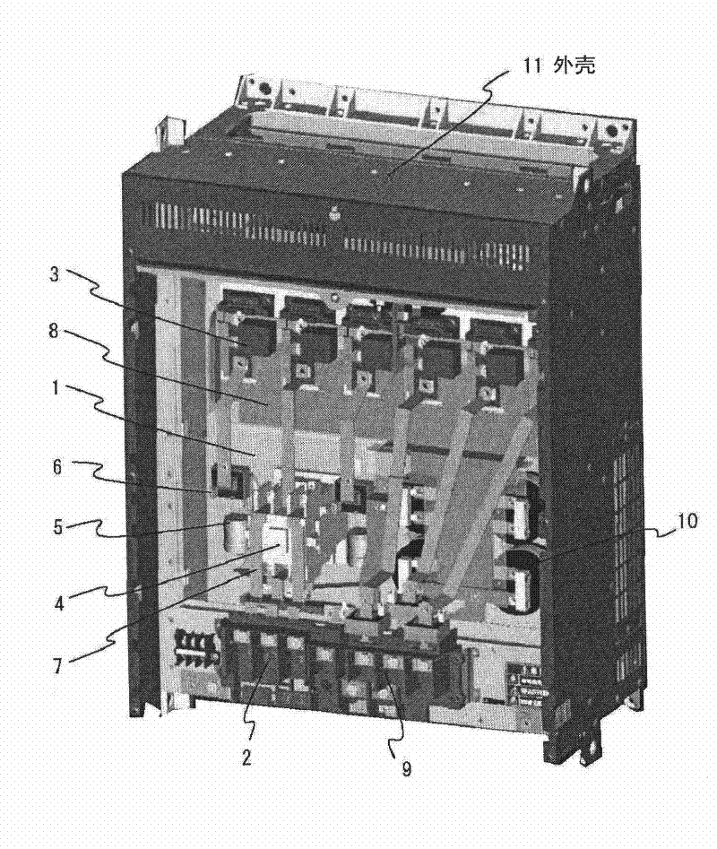
[0025] Below, based on figure 1 A~ image 3 The illustrated examples describe the implementation of the invention. For with Figure 4 ~ Figure 7 Components in the corresponding embodiment figures are given the same reference numerals and numerals, and descriptions thereof are omitted.

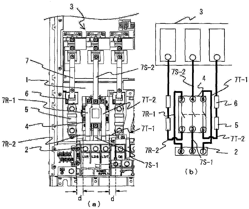
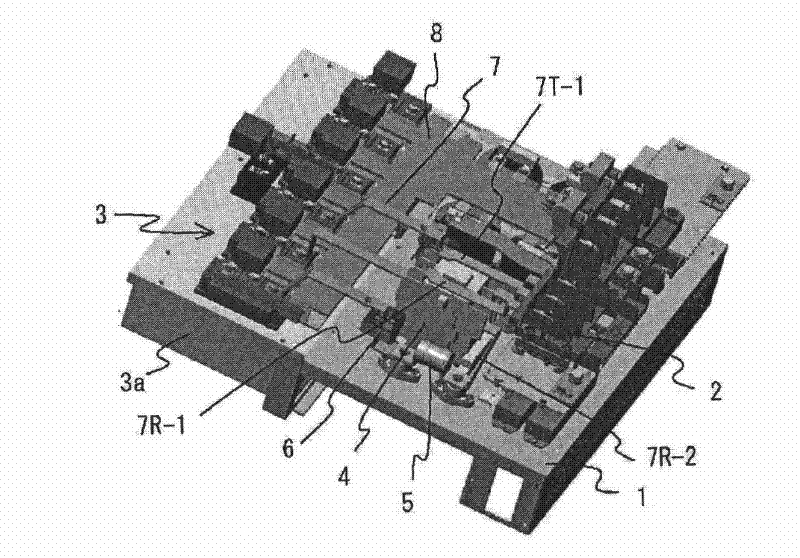
[0026] figure 1 A. figure 1 B. and figure 2 The layout of the main circuit components shown is basically the same as Figure 6 and Figure 7 As in the comparative example 2 shown, the series connection body of the fuse 5 and the input CT 6 between the R phase and the T phase of the input power supply is arranged side by side across the left and right sides of the electromagnetic contactor 4, but from the input terminal block 2. The wiring path of the bus bar connected to the fuse 5 via the electromagnetic contactor 4 is formed as follows.

[0027] That is, for the power supply R phase and T phase in which the fuse 5 and the input CT 6 are interposed, contrary to the above-mentioned ...


PUM


Abstract

To improve the layout of main circuit parts of an inverter device, and the structure of the wiring between the parts, thereby accomplishing space saving for a substrate on which the circuit parts are mounted. In an inverter device in which an electromagnetic contactor, fuses, and input CTs are disposed between a semiconductor module and input terminal block disposed at upper and lower end portions of a substrate, and the parts are interconnected by a bus bar, with the electromagnetic contactor disposed with primary side terminals and secondary side terminals thereof facing the input terminal block and semiconductor module respectively, and the fuses and input CTs serially connected and arranged in parallel to the sides of the electromagnetic contactor, an R-phase and T-phase passing through the fuses and input CTs are such that the power source input terminals and the secondary side terminals of the electromagnetic contactor are connected by bus bars 7R-1 and 7T-1, and the primary side terminals of the electromagnetic contactor and the fuses are connected by bus bars 7R-2 and 7T-2, thus reducing the intervals between the electromagnetic contactor and the fuses, and accomplishing a space saving for the substrate.

Description

technical field [0001] The present invention relates to a general-purpose inverter device with a built-in electromagnetic contactor applied to, for example, elevator equipment, and more particularly to a wiring structure of main circuit components mounted on a substrate in a casing of the inverter device. Background technique [0002] As is well known, the above-mentioned general-purpose inverter device is constituted by an assembled structure in which a main circuit board including a power input terminal block and a main circuit semiconductor module is mounted on a plate metal substrate installed in a case of the inverter device. circuit components, and these components are connected to each other by bus bars (for example, refer to JP-A-2007-312545). [0003] Also, depending on the type of inverter device, there is also known a general-purpose inverter device in which an electromagnetic contactor connected to the primary side of the main circuit is built so that the inverte...

Claims


Application Information

Patent Timeline
Patent Type & Authority Applications(China)
IPC IPC(8): H02M7/48
CPCH02M7/003H01H51/005
Inventor 鸠崎芳久中井胜
Owner FUJI ELECTRIC CO LTD
Why Eureka
Try Eureka