Light emitting diode (LED) backlight module and liquid crystal display (LCD) device

A technology for a liquid crystal display device and a backlight module, which can be applied to lighting devices, fixed lighting devices, components of lighting devices, etc., can solve problems such as wasted man-hours

Active Publication Date: 2012-02-15
TCL CHINA STAR OPTOELECTRONICS TECH CO LTD
View PDF3 Cites 34 Cited by
  • Summary
  • Abstract
  • Description
  • Claims
  • Application Information

AI Technical Summary

Problems solved by technology

This process is a waste of time

Method used


Image

  • Light emitting diode (LED) backlight module and liquid crystal display (LCD) device
  • Light emitting diode (LED) backlight module and liquid crystal display (LCD) device
  • Light emitting diode (LED) backlight module and liquid crystal display (LCD) device

Examples


Embodiment 1

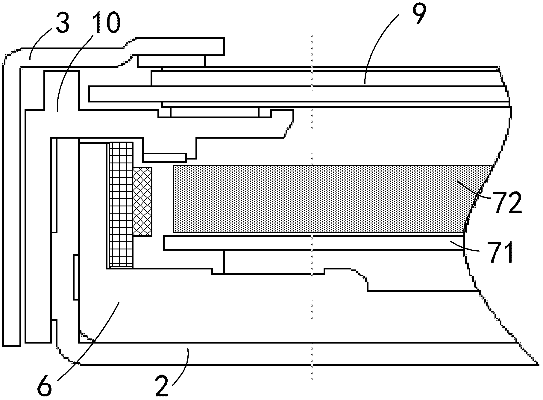
[0024] The backlight module and the liquid crystal display are fixed through the front frame 3 , preferably, the front frame 3 is fixedly connected to the light source fixing device 6 . The existing liquid crystal display device, viewed from the side from the outside to the inside, includes a front frame 3, a plastic frame 10, a back plate 2, and a light source fixing device 6, with a total of four layers of structure; while the front frame 3 and the light source in this embodiment The fixing device 6 is directly fixed and connected, and the plastic frame 10 is directly omitted, and the back plate 2 can be fixedly connected with the light source fixing device 6 behind the LED backlight module without extending to the side of the LED backlight module for fixing, so this implementation On the one hand, the method can reduce the cost; on the other hand, it can also reduce the width of the frame of the liquid crystal display device, which is in line with the trend of thinning and t...

Embodiment 2

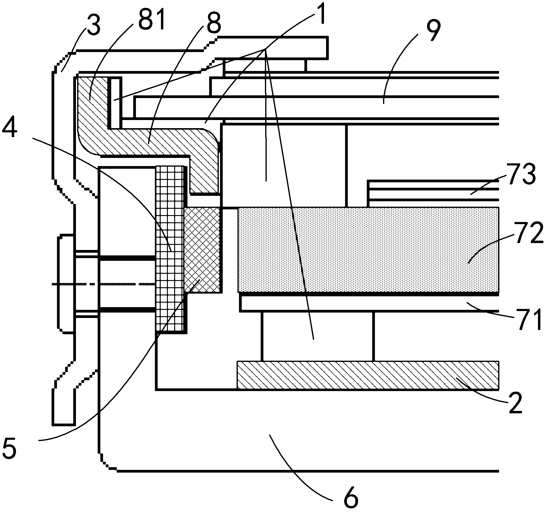
[0029] One end of the light source fixing device 6 fixing the LED5 light bar is located on the side of the light guide plate 72, and a positioning plate 8 is arranged between the top of the end and the liquid crystal display 9; 9 the first end portion 81 between the side and the front frame 3. The positioning plate 8 increases the clamping force on the liquid crystal display 9 , and the first end 81 can limit the side of the liquid crystal display 9 . Preferably, a buffer material 1 can be added on the surface of the positioning plate 8 in contact with the liquid crystal display 9 , and a buffer material 1 can also be added between the liquid crystal display 9 and the light guide plate 72 to increase the clamping force. Adding buffer material 1 to the side and bottom of the liquid crystal display 9 can give the liquid crystal display 9 better clamping force, and at the same time the liquid crystal display 9 is not easily crushed. In addition, the buffer material 1 added at th...


PUM


Abstract

The invention discloses a light emitting diode (LED) backlight module and a liquid crystal display (LCD) device. The LED backlight module comprises a lamp source fixing device used for fixing an LED lamp strip, and a back plate connected with the lamp source fixing device; and the LED backlight module is characterized in that the lamp source fixing device is connected with the back plate from the outer layer of the LED backlight module. After the LED backlight module and the LCD device are adopted, the disassembly process of an LED is greatly simplified; furthermore, an optical component is not needed to be moved when the LED is disassembled due to the structure form, so that the optical component is prevented from being damaged artificially, and the possibility that the display quality is reduced by moving can be reduced.

Description

technical field [0001] The invention relates to the display field, and more specifically, relates to an LED backlight module and a liquid crystal display device. Background technique [0002] At present, it is a market trend to use LED as a backlight source, and it is widely used in the field of liquid crystal display. The structure of an existing liquid crystal display device using an LED backlight module is as follows: figure 1 As shown, the outermost layer of the liquid crystal display device is the front frame. Counting from the side, from the outside to the inside are the plastic frame, the back plate, the aluminum extrusion, and then the PCB and LEDs that make up the LED light bar. Since the existing LEDs are located in In the innermost part of the entire backlight module, if some LEDs are broken and need to be reworked, the front frame needs to be removed, and the glass, optical film, light guide plate (LGP) and other components must be taken out to remove the LEDs. ...

Claims


Application Information

Patent Timeline
Patent Type & Authority Applications(China)
IPC IPC(8): F21S8/00F21V19/00F21V17/10G02F1/13357F21Y101/02
CPCG02B6/0085G02B6/009G02F1/133308G02F1/133615G02F2203/68G02F1/133317
Inventor 杨瑞连
Owner TCL CHINA STAR OPTOELECTRONICS TECH CO LTD
Why Eureka
Try Eureka