Passive mechanical arm collector

A mechanical arm and passive technology, applied in the direction of current collectors, non-rotating current collectors, circuits, etc., can solve problems such as rigid movements, glides, and difficulty in ensuring the level of the bottom surface, and achieve improved safety, balanced pressure, and balanced contact area. Effect

Inactive Publication Date: 2013-05-01
江苏江鹤滑线电气有限公司
View PDF5 Cites 0 Cited by
  • Summary
  • Abstract
  • Description
  • Claims
  • Application Information

AI Technical Summary

Problems solved by technology

This kind of collector is usually over-moving and stiff, and it is prone to bumps, scratches, bouncing, or derailment when passing through the connection of the power line (sliding contact line) or turning.
[0003] This is because it is difficult for each part to work in an ideal state during the actual work.
For example, at a bend, when the brush is running with the trolley, it is difficult to ensure the level of the bottom surface due to the centrifugal force; in the long-distance transmission, due to thermal expansion and contraction, it is difficult to ensure that the rigid sliding contact wire is equipped with an anti-expansion device. The overall level of the working surface
In this way, the electric receiving surface of the brush cannot maintain a balanced area in contact with the working surface of the trolley line during the movement.

Method used


Image

  • Passive mechanical arm collector
  • Passive mechanical arm collector
  • Passive mechanical arm collector

Examples


Embodiment Construction

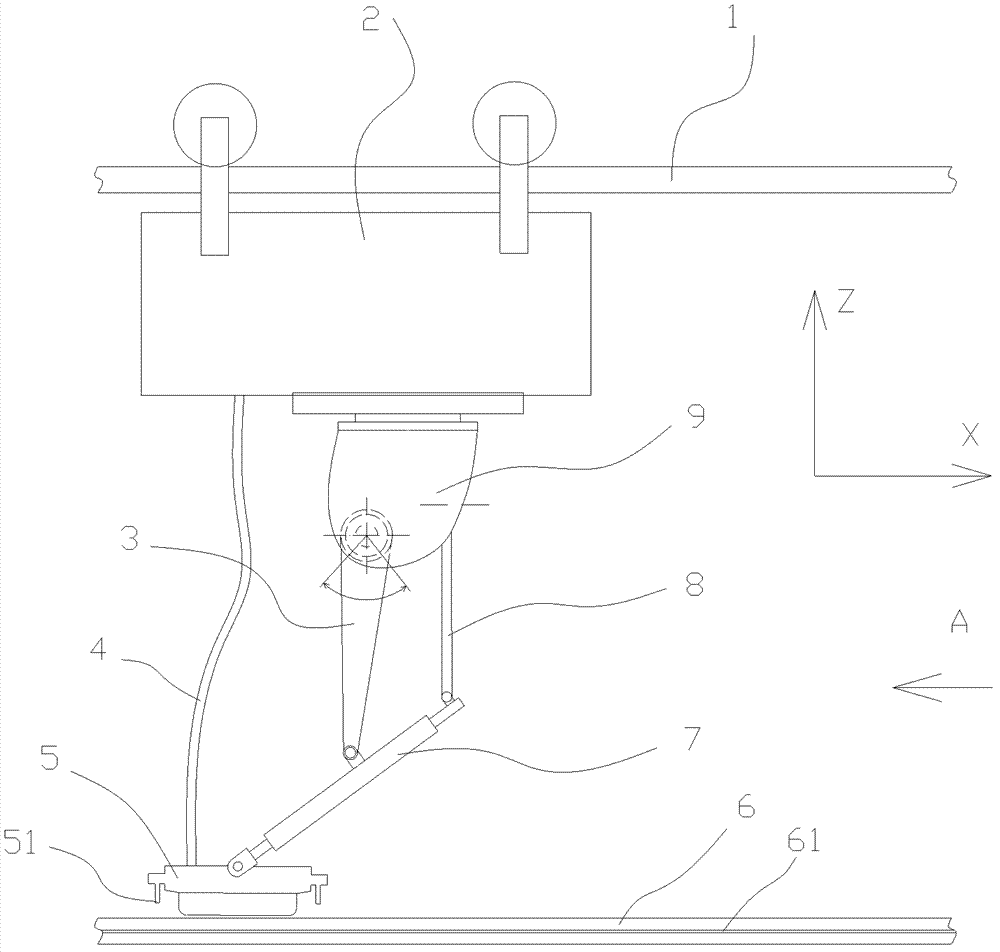
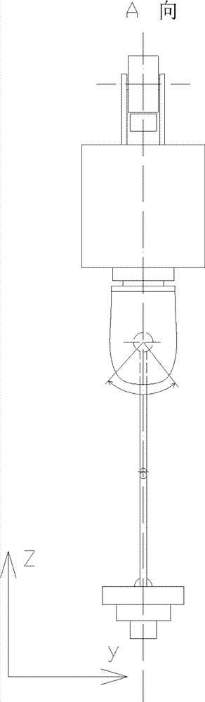
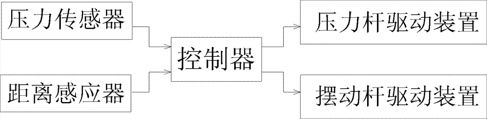
[0022] Such as Figure 1-3 As shown, the present invention includes a trolley 2 running on a guide rail 1, a conductive belt 4, a collector arm 7 and a block-shaped brush 5 kept in contact with the trolley line 6, and the collector arm 7 is connected to the collector arm 7 through a passive mechanical device. The trolley 2 is connected; the passive mechanical device includes a housing 9, a controller, a pressure rod 3 and its driving device, a swing rod 8 and its driving device, a pressure sensor and a distance sensor 51;

[0023] The housing 9 is fixedly connected to the trolley 2, and the controller, the pressure rod driving device and the swing rod driving device are arranged in the housing 9; the two ends of the pressure rod 5 are respectively connected to the between the pressure rod driving device and the middle part of the collector arm 7; the two ends of the swing rod 8 are respectively connected between the swing rod drive device and the tail of the collector arm 7 th...


PUM


Abstract

The invention relates to a trolley conductor collector applied to unbalance loading and curve places, and provides a passive mechanical arm collector, which passively keeps an electric brush working surface and a trolley conductor working surface having balanced powered areas according to the conditions of the trolley conductor working surface. The collector comprises a trolley, a conductive band, a current collection arm and a blocky electric brush keeping in contact with a trolley conductor. In the collector, an additional passive mechanical device is arranged between the current collectionarm and the electric brush to regulate the working conditions of the electric brush by acquiring position information in real time. The current collection arm is provided with two connecting parts relative to a 'base' or shell, a pressure rod can oscillate in an XZ coordinate plane and an oscillating rod can oscillate in a YZ plane, so that a contact area is balanced and pressure is balanced. By the passive mechanical arm collector, stable power transmission is ensured, and simultaneously, the electric brush can be ensured not to be deviated and separated from the trolley conductor and changethe contact area to further improve the running safety, stability and reliability of equipment.

Description

technical field [0001] The invention relates to a trolley line collector with power supply guiding function, in particular to a trolley line collector applied to the occasions of eccentric loads and curved roads. Background technique [0002] The current collector is a power receiving device that transmits electric energy from the power line to the mobile power consumption device. It ensures the normal power supply of the power consumption equipment through uninterrupted sliding contact. In order to achieve the above effects, carbon-containing metal blocks (brushes) are usually used to enhance the sliding contact force, and elastic springs are used to control the tension between the current collector and the sliding wire, and a fixed bracket is used to weld the current collector. Bind with the device. This kind of collector is usually over-moving and stiff, and it is prone to bumping, scratching, bouncing, or derailment when passing through the connection of the power line ...

Claims


Application Information

Patent Timeline
Patent Type & Authority Patents(China)
IPC IPC(8): H01R41/00
Inventor 华鹤章董永军
Owner 江苏江鹤滑线电气有限公司
Why Eureka
Try Eureka