Direct-current charging system

A DC charging and charging machine technology, applied in the direction of collectors, electric vehicles, electrical components, etc., can solve the problems of inability to connect the power line to the public grid, no human-computer interface, limited power battery power, etc., to improve data Reliability and operational safety, shortened charging times, increased enthusiasm for use

Inactive Publication Date: 2012-02-15
大连罗宾森电源设备有限公司
View PDF8 Cites 7 Cited by
  • Summary
  • Abstract
  • Description
  • Claims
  • Application Information

AI Technical Summary

Problems solved by technology

For electric products whose location does not move frequently, the power line can be connected to the public grid (the AC voltage of the public grid described in this application document is 380V) for a long time to obtain the power required for operation; however, for frequently changing locations For electric products (such as mobile phones, electric bicycles, electric vehicles, etc.), the power line cannot be connected to the public grid all the time, and most of the time it can only be maintained by the power battery; and the power battery can store is limited , often there will be insufficient power during use, so the charging station came into being
At present, most of the existing charging stations only provide a few simple charging interfaces and do not have a human-computer interaction interface. They can only charge low-power electric products such as mobile phones, and the charging efficiency is low. payment method, so it is very inconvenient to use and has great limitations

Method used


Image

  • Direct-current charging system
  • Direct-current charging system
  • Direct-current charging system

Examples


Embodiment 1

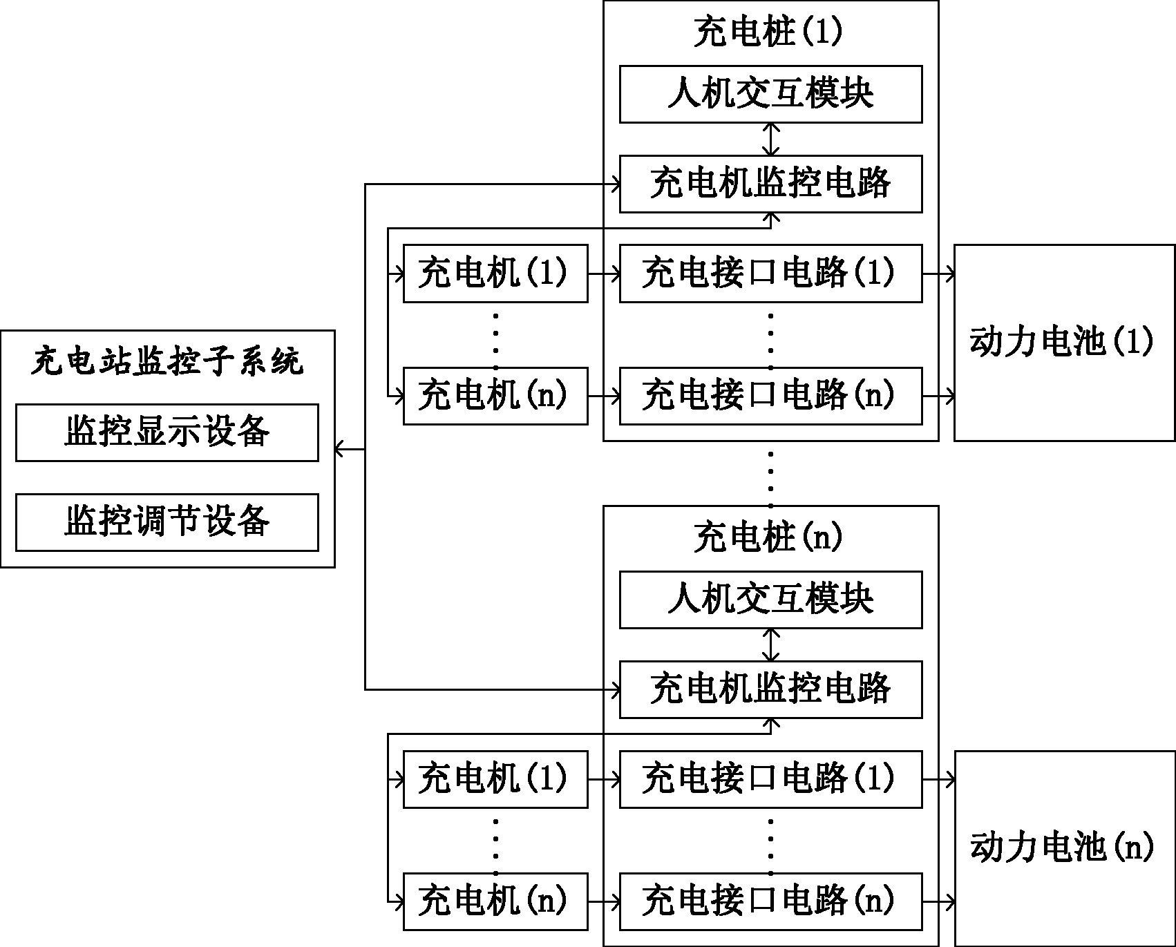
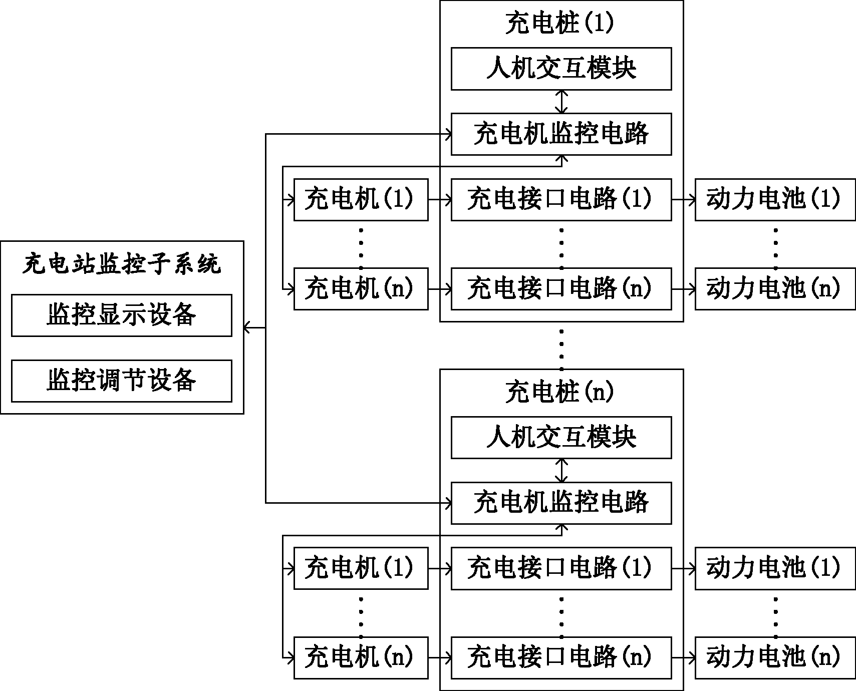
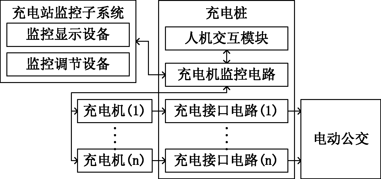
[0034] Such as image 3 and Figure 4 As shown, a DC charging system is used to obtain electric energy from the public grid and charge the power battery of a pure electric bus. Its specific structure may include: a charging station monitoring subsystem, a charging pile, and two chargers (ie The first charging machine and the second charging machine); the corresponding charging pile includes two charging interface circuits, a charging machine monitoring circuit with PLC as the core, and a human-computer interaction circuit with a color touch screen as the core;

[0035] Wherein, the first charger and the second charger are provided with a current input terminal, a current output terminal and a data transmission terminal; the current input terminals of the first charger and the second charger are connected to the public power grid, Electric energy is obtained from the power grid; the data transmission terminals of the first charger and the second charger are connected to the ch...


PUM


Abstract

The invention relates to a direct-current charging system, which is used for acquiring electric energy from a public electric network and charging a power battery, and comprises a charging station monitoring subsystem, at least one charging pile and at least two charging machines; each charging pile comprises a charging machine monitoring circuit and at least two charging interface circuits, and each charging interface circuit is connected with one charging machine; each charging machine is provided with a current input end, a current output end and a data transmission end; the current input end is connected with the public electric network; the current output end is connected with the charging interface circuit; the data transmission end is connected with the charging machine monitoring circuit; and the charging machine monitoring circuit of each charging pile is connected with the charging station monitoring subsystem. Due to the realization of the embodiment of the direct-current charging system, a human-machine interactive interface which is convenient for users to use is provided, the charging efficiency can be greatly improved, a pure-electric bus can be quickly charged, and the minimal time for fully charging a power battery of the pure-electric bus is only 10 minutes; and at the same time, the entire charging process can be instantly monitored, and the application safety can be improved.

Description

technical field [0001] The invention belongs to the technical field of charging, and in particular relates to a direct current charging system. Background technique [0002] With the advancement of science and technology and the enhancement of environmental awareness, various electrical products are found in every corner of people's production and life. For electric products whose location does not move frequently, the power line can be connected to the public grid (the AC voltage of the public grid described in this application document is 380V) for a long time to obtain the power required for operation; however, for frequently changing locations For electric products (such as mobile phones, electric bicycles, electric vehicles, etc.), the power line cannot be connected to the public grid all the time, and most of the time it can only be maintained by the power battery; and the power battery can store is limited , There will often be insufficient power during use, so charg...

Claims


Application Information

Patent Timeline
IPC IPC(8): H02J7/00B60S5/00
Inventor 程卫平魏东升
Owner 大连罗宾森电源设备有限公司
Why Eureka
Try Eureka