High speed DAC current source switch driving circuit

A switch drive circuit, drive circuit technology, applied in the direction of electronic switches, electrical components, pulse technology, etc., can solve the problems of reducing DAC conversion rate, output burr peaks, etc., to reduce the feedthrough effect, overcome burrs and distortion, avoid effect of influence

Inactive Publication Date: 2012-02-15
SUZHOU R&D CENT OF NO 214 RES INST OF CHINA NORTH IND GRP
View PDF2 Cites 11 Cited by
  • Summary
  • Abstract
  • Description
  • Claims
  • Application Information

AI Technical Summary

Problems solved by technology

At this time, if the threshold voltage of the PMOS transistor |V T |Below the intersection point of the control signal, then when the current switch switches, at a certain moment the two switch tubes will be turned off at the same time, causing the current source tube to also turn off and output a glitch peak at the output
In addition, it takes a long time for the current source tube to return from the off state to the on state, which reduces the conversion rate of the DAC.

Method used


Image

  • High speed DAC current source switch driving circuit
  • High speed DAC current source switch driving circuit
  • High speed DAC current source switch driving circuit

Examples


Embodiment 1

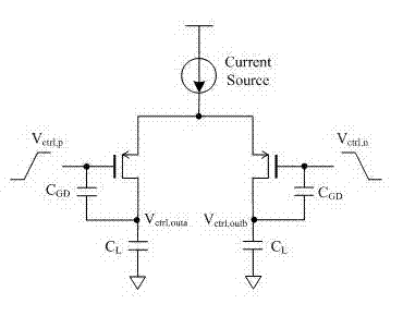
[0043] Embodiment 1: a high-speed DAC current source switch drive circuit, the power supply voltage Sub_VDD of the drive circuit is a limiter power supply, and the power supply voltage Sub_VDD of the drive circuit is 1.8V. The power supply voltage Sub_VDD of the driving circuit is lower than the power supply voltage VDD. The limiting power supply obtains a relatively low amplitude of the switch control signal, which speeds up the switching speed of the current switch, improves the conversion rate of the chip, and reduces the control signal passing through the gate-drain overlap capacitance C GD The generated feedthrough effect reduces the instantaneous burr generated.

[0044] The drive circuit includes

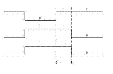
[0045] The signal synchronization unit is used to ensure the synchronization of the current switch control signals. The signal synchronization unit generates a set of complementary first control signals D, DN, and a set of complementary second control signals DS, DSN;

[00...


PUM


Abstract

The invention relates to a high speed DAC current source switch driving circuit. A power supply voltage of the driving circuit is lower than a power supply voltage. The power supply of the driving circuit is an amplitude limit power supply. The driving circuit comprises a signal synchronization unit which is used for guaranteeing synchronization of current switch control signals. The signal synchronization unit gates the switch control signals through a global clock (CLK) and performs synchronization latch through a latch unit so that the synchronization of all the current switch control signals can be guaranteed. The signal synchronization unit generates a group of complementary first control signals and a group of complementary second control signals. A reduction control voltage cross point unit outputs two channels of control voltages and is used to reduce cross points of the two channels of control voltages so that the two complementary current switches can not be turned off simultaneously. An output terminal can avoid to output burr and peak. Smooth transition of the output current can be realized. By using the circuit of the invention, the burr and the peak introduced by the current switch can be overcome; influence of the current source switch control signals on DAC performance can be avoided.

Description

technical field [0001] The invention relates to a high-speed DAC current source switch driving circuit. Background technique [0002] With the rapid development of mobile communication, broadband communication systems, especially in systems requiring direct intermediate frequency or higher baseband performance, W-CDMA base stations, multi-carrier base stations, multi-frequency cables and other systems, the demand for high-speed, high-precision DAC is increasing. more and more widely. [0003] Commonly used DAC structures are current type, voltage type and charge type. Because the current-type DAC directly outputs the current, it does not need to convert the current to the voltage, so the speed is relatively fast; the current-type DAC can be divided into weighted resistance type, weighted resistance network type with group attenuation, R-2R ladder resistance type, current Rudder type. Because the current steering DAC has its inherent advantages over other types of DACs, it...

Claims


Application Information

Patent Timeline
Patent Type & Authority Applications(China)
IPC IPC(8): H03K17/687H03K17/042
Inventor 刘德状王少轩
Owner SUZHOU R&D CENT OF NO 214 RES INST OF CHINA NORTH IND GRP
Why Eureka
Try Eureka