Display panel and display device

A display panel and display area technology, applied in optics, instruments, nonlinear optics, etc., can solve the problems of low light utilization efficiency, achieve the effect of improving light utilization efficiency and suppressing the decline of contrast

Inactive Publication Date: 2012-02-15
SHARP KK
View PDF6 Cites 28 Cited by
  • Summary
  • Abstract
  • Description
  • Claims
  • Application Information

AI Technical Summary

Problems solved by technology

[0005] However, in the conventional display device, in each display area, the color filter blocks two colors of light among red light, green light and blue light, so there is a problem of low light utilization efficiency.

Method used


Image

  • Display panel and display device
  • Display panel and display device
  • Display panel and display device

Examples


no. 1 Embodiment approach

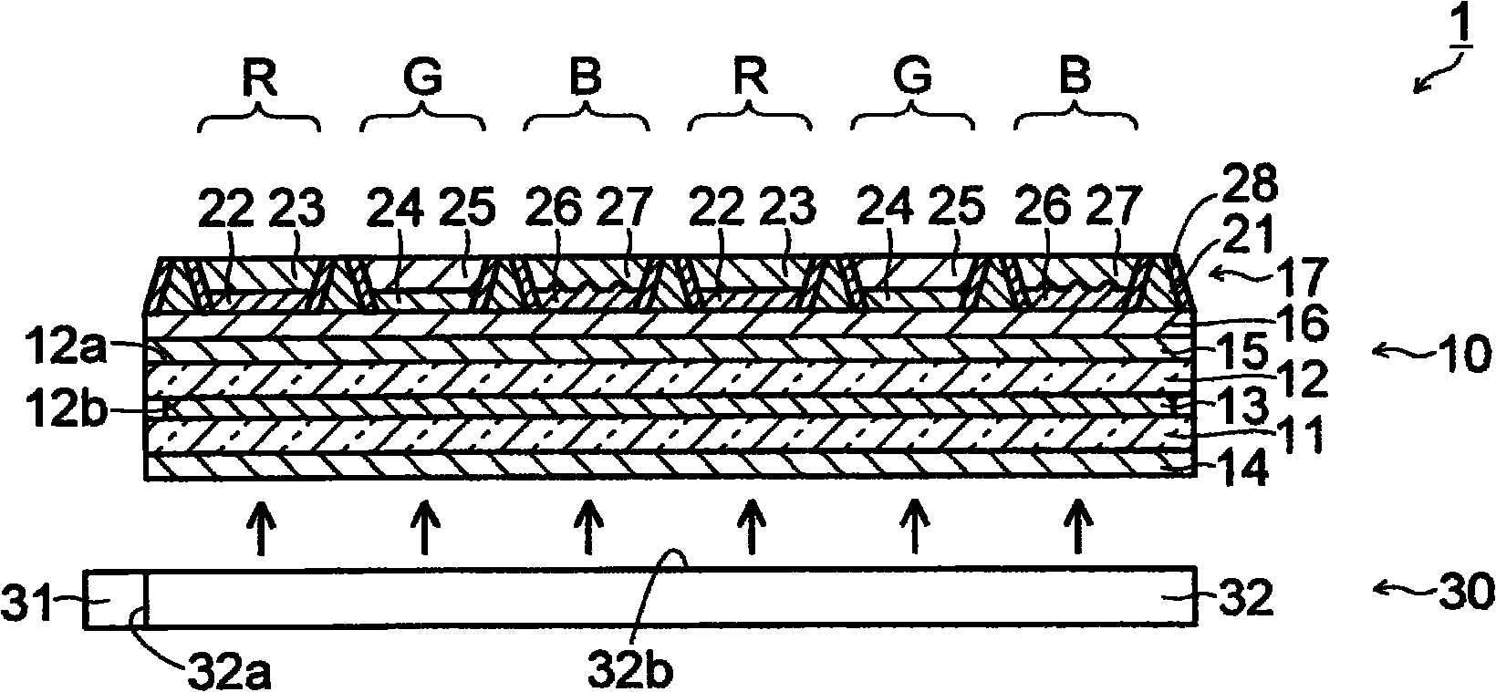
[0061] refer to Figure 1 ~ Figure 4 Next, the configuration of the liquid crystal display device 1 including the liquid crystal display panel 10 according to the first embodiment of the present invention will be described.

[0062] Such as figure 1 As shown, the liquid crystal display device 1 of the first embodiment of the present invention includes: a liquid crystal display panel 10; a backlight unit 30, which is arranged on the back side of the liquid crystal display panel 10, and irradiates blue light to the liquid crystal display panel 10; A frame (not shown) of the liquid crystal display panel 10 and the backlight unit 30 . In addition, the liquid crystal display device 1 is an example of the "display device" of the present invention, and the liquid crystal display panel 10 is an example of the "display panel" of the present invention.

[0063] The liquid crystal display panel 10 includes: an AM substrate (active matrix substrate) 11; an opposite substrate (opposite ...

no. 2 Embodiment approach

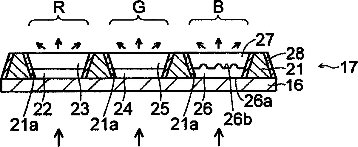
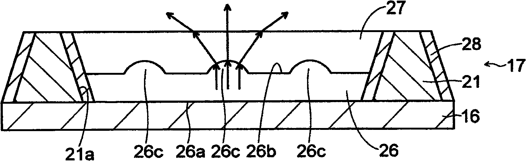
[0109] In the second embodiment, refer to Figure 5 ~ Figure 7 Next, a case where a plurality of convex portions 56c are formed on the light-emitting surface 56b of the transparent resin layer 56, unlike the first embodiment described above, will be described.

[0110] In the color filter 47 of the liquid crystal display panel of the second embodiment of the present invention, such as Figure 5 As shown, a transparent resin layer 56 and a blue filter layer 57 are formed in the opening 21a of the blue display region B. As shown in FIG. Furthermore, the “blue transmission layer” of the present invention is constituted by the transparent resin layer 56 and the blue filter layer 57 . In addition, the transparent resin layer 56 is an example of the "light-diffusion layer" of this invention. In addition, the blue filter layer 57 is an example of "a layer in contact with the surface on which at least one of the plurality of protrusions and the plurality of recesses is formed" in th...

no. 3 Embodiment approach

[0117] In the third embodiment, refer to Figure 8 Next, the case where both the plurality of convex portions 76c and the plurality of concave portions 76d are formed on the light exit surface 76b of the transparent resin layer 76, unlike the first and second embodiments described above, will be described.

[0118] In the color filter 67 of the liquid crystal display panel of the third embodiment of the present invention, as Figure 8As shown, a transparent resin layer 76 and a blue filter layer 77 are formed in the opening 21a of the blue display region B. As shown in FIG. Furthermore, the “blue transmission layer” of the present invention is constituted by the transparent resin layer 76 and the blue filter layer 77 . In addition, the transparent resin layer 76 is an example of the "light-diffusion layer" of this invention. The blue filter layer 77 is an example of the "layer in contact with the surface on which at least one of the plurality of protrusions and the plurality...


PUM


Abstract

Disclosed is a liquid crystal display panel wherein the utilization efficiency of light can be improved, while suppressing deterioration of the contrast. Specifically, a color filter (17) of a liquid crystal display panel (10) comprises: a black matrix (21) which is provided with an opening (21a); a red phosphor layer (22) and a red filter layer (23) which are arranged within the opening (21a) in a red display region (R); a green phosphor layer (24) and a green filter layer (25) which are arranged within the opening (21a) in a green display region (G); and a transparent resin layer (26) and a blue filter layer (27) which are arranged within the opening (21a) in a blue display region (B). A light exit surface of the transparent resin layer (26) is provided with a plurality of projected portions (26c), and the transparent resin layer (26) has a refractive index different from that of the blue filter layer (27), which is in contact with the light exit surface. The transparent resin layer (26) is a light diffusion layer, and is capable of increasing the viewing angle of blue light.

Description

technical field [0001] The present invention relates to a display panel and a display device. Background technique [0002] Conventionally, there is known a display device including a backlight device that emits (emits) white light, and a display panel that is irradiated with the light emitted from the backlight device. In such a display device, a display panel includes, for example, a pair of substrates sandwiching a liquid crystal or the like, and a color filter arranged on a light incident side or a light emitting side of the pair of substrates. [0003] The color filter is formed with: a red filter layer that blocks green light and blue light and transmits red light; a green filter layer that blocks red light and blue light and passes green light; and a red filter layer that blocks red light and green light. Blue filter layer that transmits blue light. The red filter layer, the green filter layer and the blue filter layer are respectively formed in the red display area...

Claims


Application Information

Patent Timeline
Patent Type & Authority Applications(China)
IPC IPC(8): G02F1/1335G02B5/20
CPCG02B5/201G02F1/133504G02F1/133512G02F1/133617G02F1/133562
Inventor 门胁真也石田壮史甲斐田一弥八代有史国政文枝重田博昭结城龙三
Owner SHARP KK
Why Eureka
Try Eureka