Method for determining fittings for constant tables of automatic placement machines

A workbench, automatic machine technology, applied in the direction of electrical components, electrical components, etc., can solve the problems of unsatisfactory results and high time consumption, and achieve the effects of reducing storage requirements, optimizing manufacturing processes, and reducing space

Active Publication Date: 2012-02-15
SIEMENS AG
View PDF7 Cites 21 Cited by
  • Summary
  • Abstract
  • Description
  • Claims
  • Application Information

AI Technical Summary

Problems solved by technology

The time consumption associated with this is ve

Method used


Image

  • Method for determining fittings for constant tables of automatic placement machines
  • Method for determining fittings for constant tables of automatic placement machines

Examples


Embodiment Construction

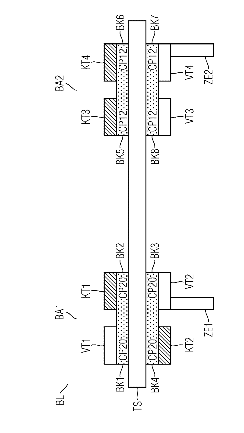
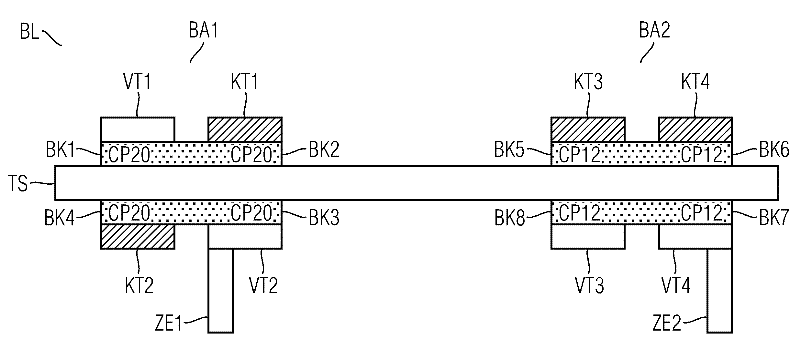
[0036] figure 1 An exemplary expansion of an assembly line BL with two assembly robots BA1 and BA2 , which are arranged on a transport system TS (for example a conveyor belt), is shown.

[0037] The assembly robot BA1 consists of 4 transfer tables KT1 , KT2 , VT1 , VT2 , two of which are variable tables VT1 , VT2 and two of which are constant tables KT1 , KT2 . Furthermore, the assembly robot BA1 consists of four assembly heads BK1-BK4 each of the CP20™ type. The assembly heads BK1-BK8 of the assembly robot BA1, BA2 pick up components from the conveyors ZE1, ZE2 and move these components to the assembly area of ​​the assembly robot BA1, BA2, where substrates to be assembled are provided (e.g. in SMD manufacturing substrate), and the components are placed on the substrate. Assembly heads BK1-BK8 are generally movable by positioning systems. As the conveyor devices ZE1 , ZE2 for supplying components, for example, a so-called belt feeder can be used.

[0038] An assembly robo...


PUM


Abstract

The invention relates to a method for determining fittings for constant tables of automatic placement machines in placement lines at predetermined table locations by means of mixed integer linear optimization based on input data describing the placement infrastructure and input parameters that can be specified by the operator or user. The method can be used regardless of the mounting technique used (for example, plug in mounting technique, surface mounting technique, or a hybrid technique). The method can be advantageously used with other methods, for example, cluster methods for forming fitting groups or line balancing for cycle time optimization.

Description

technical field [0001] The invention relates to a method for determining, at a fixedly predetermined workstation location, the equipment of a constant workstation for assembling a robot in an assembly line, wherein the equipment of the constant workstation is used in all equipment groups , where the equipment family includes the set of shares (Los) made within the equipment. [0002] Furthermore, the invention relates to an assembly robot comprising an invariant table whose configuration can be determined by the method according to the invention. Background technique [0003] An assembly line is a plurality of assembly robots, usually connected by a transportation system and acting together, for example, to manufacture electronic parts. [0004] In an assembly robot, for example, for assembling components to substrates, a transport device for the components is arranged laterally on the transport section for the substrates. The assembly head of the assembly robot, which can...

Claims


Application Information

Patent Timeline
IPC IPC(8): H05K13/00H05K13/08
CPCH05K13/085
Inventor P.鲍尔A.普法芬格C.罗耶
Owner SIEMENS AG
Why Eureka
Try Eureka