
Turbine reaction composite vertical mill

A compound vertical mill technology, which is applied in the field of material grinding machinery and equipment, can solve the problems of unstable turbine operation, left and right shaking, different degrees of turbine wear, difficulty in achieving stable operation and large-scale equipment, and achieve small power matching, The effect of improving grinding efficiency and improving stability

Active Publication Date: 2012-02-22
刘国俊 +1
View PDF9 Cites 9 Cited by
  • Summary
  • Abstract
  • Description
  • Claims
  • Application Information

AI Technical Summary

Problems solved by technology

The turbine with this structure is connected to the cantilever output shaft of the motor, and because the materials received by the turbine cannot fall completely evenly, and the degree of wear of the turbine is different, the turbine is sometimes subject to a large eccentric force. The turbine connected to the cantilever shaft It will run unstable and shake left and right, and due to stability problems, it is difficult to achieve stable operation and large-scale equipment

Method used


Image

  • Turbine reaction composite vertical mill
  • Turbine reaction composite vertical mill
  • Turbine reaction composite vertical mill

Examples


Embodiment Construction

[0036] The present invention will be further described in detail below in conjunction with the accompanying drawings and specific embodiments.

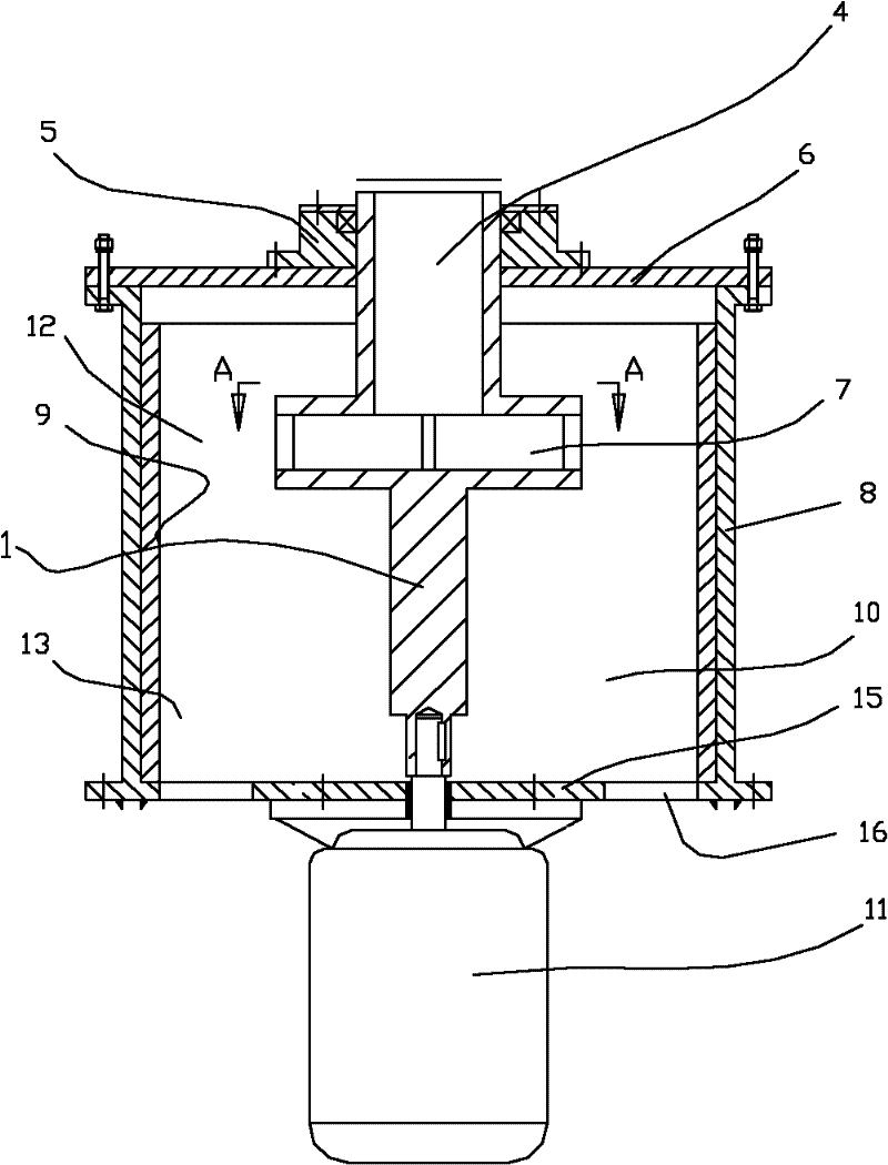
[0037] Such as figure 1 Shown: the turbine impact compound vertical mill of the present invention (also can be referred to as Liu's mill ) Embodiment 1 includes a turbine disc 7 with a feed pipe 4 on its top, a first bearing support on the outside of the feed pipe 4 , and the bottom of the turbine disc 7 is directly connected to the output shaft of the drive motor 11 . The structure of the turbine disc 7 is: a hollow disc, with a feed opening for docking with the feed pipe in the middle of the top surface, a flat plate on the bottom surface, a material distribution blade between the upper and lower sides, and a material rejection opening on the side.

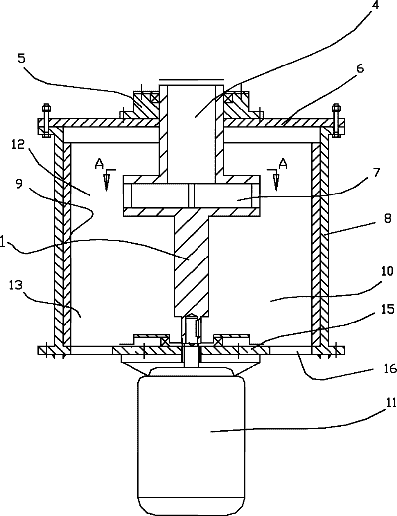
[0038] The bottom of the turbine disk 7 can also be connected with the output shaft of the drive motor after setting the second bearing support, see figure 2 Middle embodiment two. ...


PUM


Abstract

The invention relates to a turbine reaction composite vertical mill, which comprises a turbine disc, wherein a feeding pipe is arranged on the top of the turbine disc; a first bearing support is arranged outside the feeding pipe; the bottom of the turbine disc is connected with an output shaft of a driving motor directly or is provided with a second bearing support and is connected with the output shaft of the driving motor; the bottom of the turbine disc is connected with the output shaft of the driving motor directly by a lower end part with a middle shaft which extends downwards or is provided with the second bearing support and is connected with the output shaft of the driving motor; and a reaction disc is connected to the middle of the middle shaft. Two-stage crushing can be performed in the turbine reaction composite vertical mill, so under the condition of the same yield, the weight of equipment is only 3 / 5 that of 'a multi-stage turbine pulverizing mill', the height can be reduced by 1 / 2, the power matching is low, and power consumption can be reduced further, namely the power consumption of the vertical mill is between 5 and 6 kw h / t, and the power consumption of the multi-stage turbine pulverizing mill is more than or equal to 9 kw h / t; and the fineness of products can be higher, namely can be over 400 meshes, the pulverizing efficiency is improved greatly, the unit cost is lower, the investment can be saved, the centering and stability of a main shaft are ensured, and necessary conditions are provided for large-scale equipment.

Description

technical field [0001] The invention belongs to the technical field of material grinding machinery and equipment, and in particular relates to a turbine counterattack compound vertical mill. Background technique [0002] The structure of the existing vertical turbine pulverizer generally includes: a crushing chamber, and a motor located below is connected to the turbine above by its output shaft key. [0003] The material falls into the turbine from above and is centrifugally thrown by the blades of the turbine to the wall of the crushing chamber to be crushed. The turbine with this structure is connected to the cantilever output shaft of the motor, and because the materials received by the turbine cannot fall completely evenly, and the degree of wear of the turbine is different, the turbine is sometimes subject to a large eccentric force. The turbine connected to the cantilever shaft It will run unstable and shake left and right, and due to stability problems, it is diffi...

Claims


Application Information

Patent Timeline
Patent Type & Authority Applications(China)
IPC IPC(8): B02C19/00
Inventor 刘国俊刘桂桐
Owner 刘国俊
Learn More