Drilling bit centering mechanism for rotary numerical control drilling machine

A technology of CNC drilling machine and centering mechanism, which is applied in the direction of positioning measurement in boring machine/drilling machine, drilling/drilling equipment, components of boring machine/drilling machine, etc. , the problem of high cost of use, to achieve the effect of simple structure, low production cost, and improved accuracy

Inactive Publication Date: 2015-10-14
十堰方石汽车零部件有限公司
View PDF0 Cites 0 Cited by
  • Summary
  • Abstract
  • Description
  • Claims
  • Application Information

AI Technical Summary

Problems solved by technology

However, in actual use, this equipment can only use special drill bits with self-centering ability. Special equipment is required for grinding, and the grinding technology is complicated. Some users can only return to the factory for grinding, and the use cost is extremely high.
The use of ordinary twist drills is unstable in centering, and qualified products cannot be guaranteed to be processed.

Method used


Image

  • Drilling bit centering mechanism for rotary numerical control drilling machine
  • Drilling bit centering mechanism for rotary numerical control drilling machine
  • Drilling bit centering mechanism for rotary numerical control drilling machine

Examples


Embodiment Construction

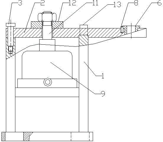
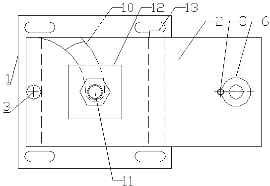
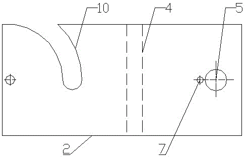
[0011] Such as figure 1 , figure 2 , image 3 and Figure 4 As shown, a drill bit centering mechanism for a rotary numerical control drilling machine includes a bracket 1 that can be fixed on the drilling machine, and a drilling template 2 is arranged above the bracket 1, wherein the rear end of the drilling template 2 is connected to the bracket 1 through a cylindrical pin 3, The bottom surface of the drill template 2 is provided with a drill template positioning groove 4 cooperating with the positioning block on the support 1, and the front end plate of the drill template 2 is provided with a drill template cover hole 5, and the drill template cover hole 5 cooperates with the drill template cover 6. The jig cover 6 is positioned in the jig cover hole 5 through the step at its upper end, and the jig cover stop pin hole 7 is arranged on the drill template 2 plate surface near the jig cover 6, and is arranged in the jig cover stop pin hole 7 The stop pin 8 is matched with t...


PUM


Abstract

The invention discloses a drilling bit centering mechanism for a rotary numerical control drilling machine, which comprises a bracket capable of being fixed at the drilling machine, wherein a drilling die plate is arranged on the bracket; the rear end of the drilling die plate is connected with the bracket by a cylindrical pin; a drilling die plate locating groove matched with a locating block on the bracket is formed in the bottom surface of the drilling die plate; a drilling die sleeve and a stop pin for stopping the drilling die sleeve are arranged on the plate surface of the front end of the drilling die plate; the bracket is internally provided with a rigidly connected hydraulic oil cylinder; a circular arc notch taking the cylindrical pin as the center is formed in the drilling die plate; a hydraulic oil cylinder piston rod penetrates through the circular arc notch to be connected with a drilling die pressing plate compressing the drilling die plate; a drilling die plate locating baffle matched with the drilling die plate is arranged on the bracket; after the hydraulic oil cylinder releases the drilling die plate, the drilling die plate can make 90-degree horizontal rotation around the cylindrical pin; and the hydraulic oil cylinder piston rod is kept away from the drilling die plate by the circular arc notch. The drilling bit centering mechanism uses the drilling die sleeve to ensure drilling bit centering, thereby realizing the effect that the machining precision of products can be ensured no matter what type of drilling bit is used.

Description

technical field [0001] The invention relates to a machine tool accessory in the field of mechanical processing and manufacturing, in particular to a drill bit centering mechanism for a rotary numerical control drilling machine. Background technique [0002] Rotary CNC drilling machine is a kind of equipment widely used in the drilling process of disc parts in the field of mechanical processing and manufacturing. It has high precision and high degree of automation, and is suitable for mass production. But in actual use, this equipment can only use a special drill bit with self-centering ability. Special equipment is required for grinding, and the grinding technology is complicated. Some users can only return to the factory for grinding, and the use cost is extremely high. The centering of ordinary twist drills is unstable, and qualified products cannot be guaranteed. Contents of the invention [0003] The invention provides a drill bit centering mechanism for a rotary nume...

Claims


Application Information

Patent Timeline
Patent Type & Authority Applications(China)
IPC IPC(8): B23B47/28B23B49/02
CPCB23B47/287B23B49/02
Inventor 韦小东
Owner 十堰方石汽车零部件有限公司
Why Eureka
Try Eureka