Multi-station oil pressure combined clamp equipment for machining upper shaft of planetary reducer

A technology of planetary reducer and combined fixture, which is applied in the direction of metal processing equipment, manufacturing tools, metal processing machinery parts, etc., can solve the problems of difficult one-person multi-machine control, low fixture life, and labor consumption, so as to avoid human factors and improve Production efficiency and the effect of releasing labor force

Inactive Publication Date: 2022-01-11
台州力聚自动化科技有限公司
View PDF0 Cites 0 Cited by
  • Summary
  • Abstract
  • Description
  • Claims
  • Application Information

AI Technical Summary

Problems solved by technology

The input shaft and output shaft need to be clamped and positioned during processing. When processing the positioning holes, the existing clamping tools use three-grip chucks to load and unload the workpiece. In order to ensure the repeated positioning accuracy of the workpiece and prevent the end face Runout, the workpiece must be calibrated with a dial indicator every time after the workpiece is loaded on the three-grip chuck; the existing clamping method takes a long time to load and unload, and the existing single-station clamping fixture refueling Frequent, long loading and unloading time cycle, labor-intensive, difficult to realize the production problem of one person multi-machine control, and the positioning accuracy is poor, the dustproof effect of the fixture is not good, and the life of the fixture is low; therefore, it is necessary to solve the above existing problems. Improve

Method used


Image

  • Multi-station oil pressure combined clamp equipment for machining upper shaft of planetary reducer
  • Multi-station oil pressure combined clamp equipment for machining upper shaft of planetary reducer
  • Multi-station oil pressure combined clamp equipment for machining upper shaft of planetary reducer

Examples


Embodiment Construction

[0033] The present invention will be further elaborated in conjunction with the accompanying drawings.

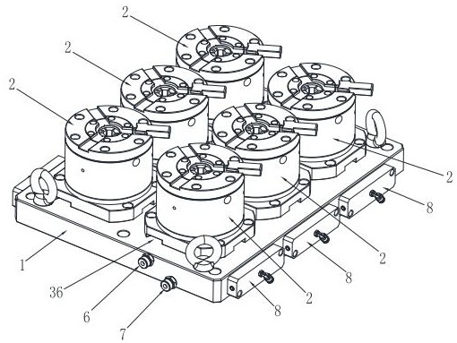
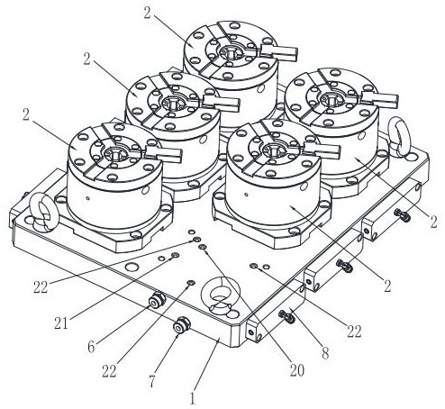
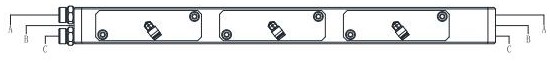
[0034] see Figure 1 to Figure 13 , the present invention provides a multi-station hydraulic combined fixture device for machining the upper shaft of a planetary reducer, which includes a large plate 1 and a number of clamping mechanisms 2 arranged on the large plate 1. The large plate 1 is provided with a number of connecting and communicating The clamping oil inlet channel 3, several connected loosening oil inlet channels 4, and several air intake channels 5; due to processing needs, several clamping oil inlet channels 3 and loosening oil inlet channels 4 are connected to the side of the large plate 1, In addition to the clamping oil inlet joint 6 corresponding to the clamping oil inlet channel 3 and the loosening oil inlet joint 7 corresponding to the loosening oil inlet channel 4 on one side of the large plate 1, the other sides of the large plate are connected. The ho...


PUM


Abstract

The invention discloses multi-station oil pressure combined clamp equipment for machining an upper shaft of a planetary reducer, which comprises a large flat plate and a plurality of clamping mechanisms arranged on the large flat plate, a plurality of connected and communicated clamping oil inlet channels, a plurality of connected and communicated loosening oil inlet channels and a plurality of air inlet channels are arranged in the large flat plate, and each clamping mechanism comprises a bottom plate, a positioning seat, a piston rod, an expansion sleeve and a backing plate; mounting holes and oil grooves are formed in the positioning seats, the piston rods are in sealed connection with the mounting holes, and oil cavity partition plates correspondingly located in the oil grooves are arranged on the piston rods; a clamping oil path, a loosening oil path and a plurality of detection gas paths are respectively arranged between parts of each clamping mechanism; and the piston rods can be pushed to move in a reciprocating mode through oil supply of the clamping oil paths and the loosening oil paths, and the detection gas paths detect whether workpieces are flatly placed by monitoring whether gas pressure leakage exists or not. The plurality of clamping mechanisms are operated through oil pressure, one-person multi-station operation is achieved, and the production efficiency is improved; and through the designed gas detection function, end faces are provided for products, and positioning is accurate.

Description

technical field [0001] The invention relates to the technical field of shaft processing fixtures, in particular to a multi-station hydraulic combination fixture device for machining upper shafts of planetary reducers. Background technique [0002] The planetary reducer is widely used in the transmission field. The input shaft and output shaft in the planetary reducer play an important role, so the processing and production quality of the input shaft and output shaft is also an important basis. The input shaft and output shaft need to be clamped and positioned during processing. When processing the positioning holes, the existing clamping tools use three-grip chucks to load and unload the workpiece. In order to ensure the repeated positioning accuracy of the workpiece and prevent the end face Runout, the workpiece must be calibrated with a dial indicator every time after the workpiece is loaded on the three-grip chuck; the existing clamping method takes a long time to load an...

Claims


Application Information

Patent Timeline
Patent Type & Authority Applications(China)
IPC IPC(8): B23Q3/00
CPCB23Q3/00B23Q2703/10
Inventor 包祖明
Owner 台州力聚自动化科技有限公司
Why Eureka
Try Eureka