
Electro-hydraulic braking device of electric locomotive

A technology for electro-hydraulic braking and electric locomotives, applied in the field of traction vehicles, can solve problems such as parking braking, and achieve the effects of improving braking efficiency, convenient hydraulic operation, and reducing maintenance costs

Inactive Publication Date: 2014-04-09
鞍钢集团(鞍山)铁路运输设备制造有限公司
View PDF7 Cites 0 Cited by
  • Summary
  • Abstract
  • Description
  • Claims
  • Application Information

AI Technical Summary

Problems solved by technology

[0005] The purpose of the present invention is to provide an electro-hydraulic braking device for electric locomotives, which omits parts such as transformers, air compressors, and air storage cylinders with large volumes, improves the reliability and stability of electric locomotive braking, and solves the problem of braking under heavy loads. Parking brake problem of small electric locomotive

Method used


Image

  • Electro-hydraulic braking device of electric locomotive
  • Electro-hydraulic braking device of electric locomotive
  • Electro-hydraulic braking device of electric locomotive

Examples


Embodiment Construction

[0015] The specific embodiment of the present invention will be further described below in conjunction with accompanying drawing:

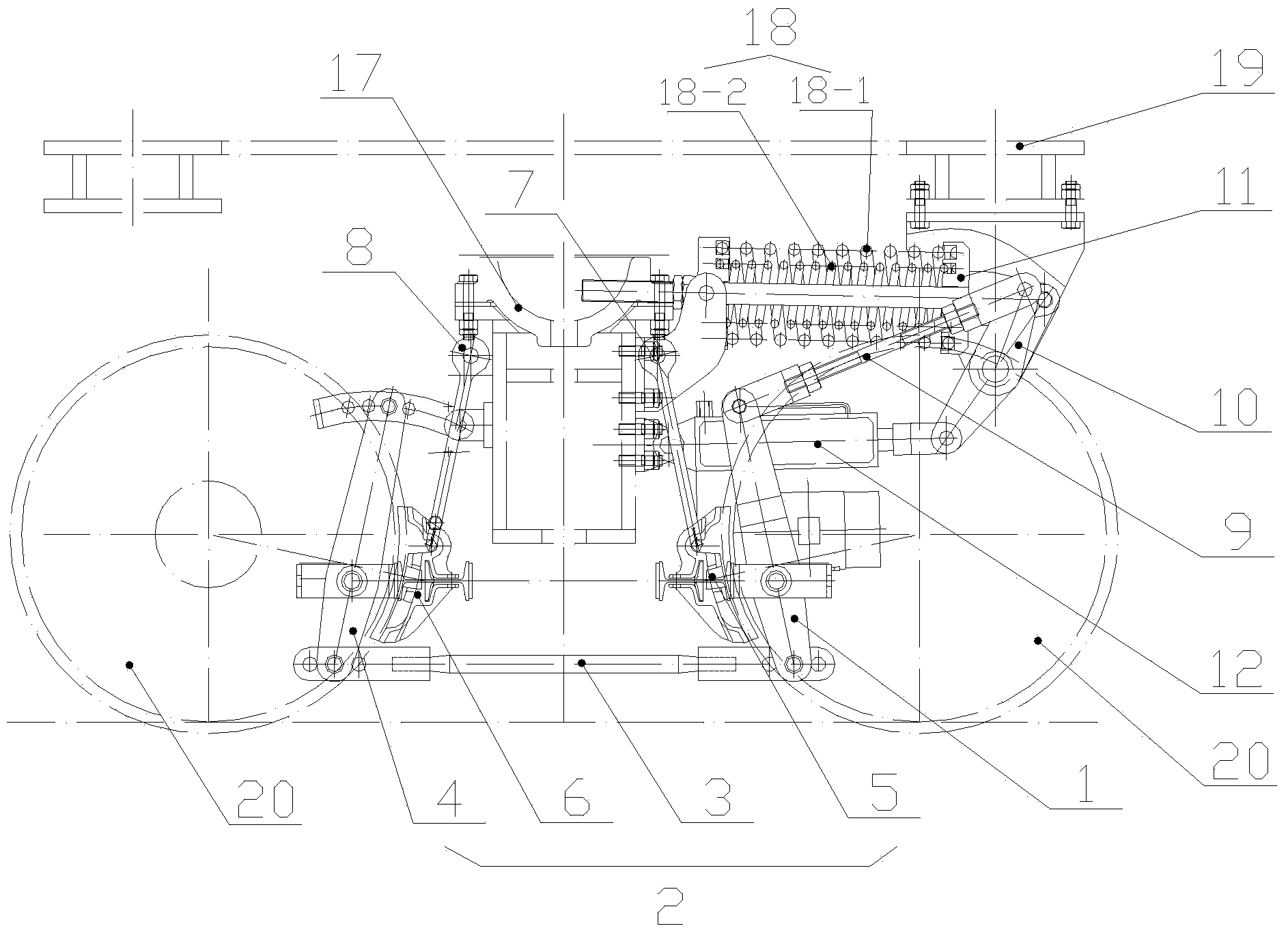
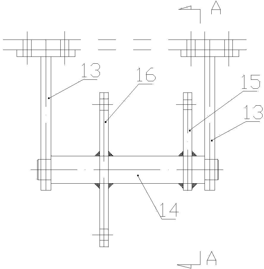
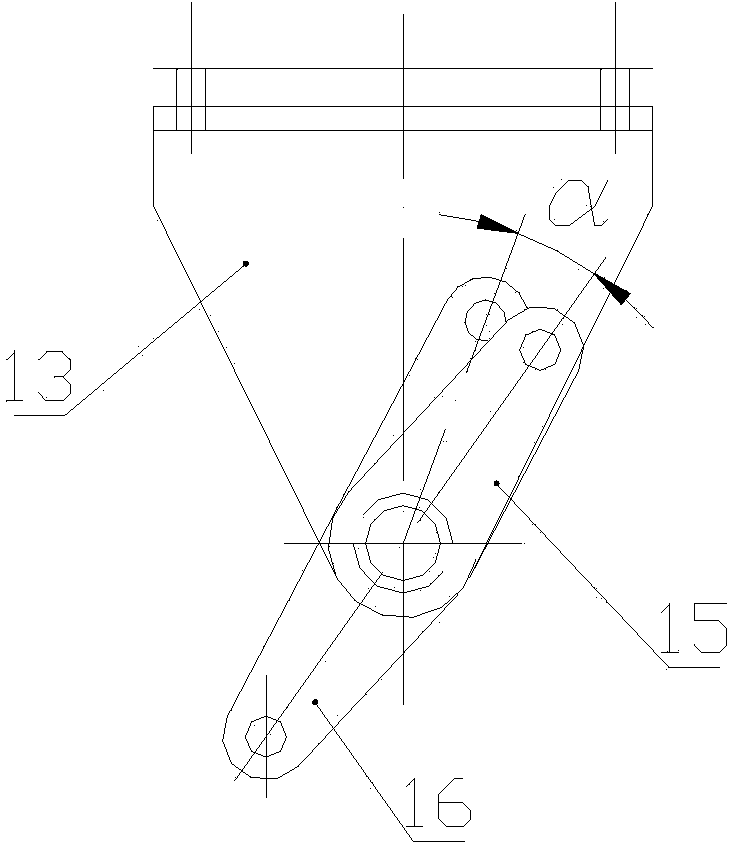
[0016] See Figure 1 to Figure 3 , which is a structural schematic diagram of an embodiment of an electro-hydraulic brake device for an electric locomotive according to the present invention, including a brake lever 1 and a linkage brake mechanism 2, and the linkage brake mechanism 2 includes a linkage lever 3, a driven brake lever 4, a brake lever Brake 1 5 and brake 2 6, brake 1 5 is hung on the frame by boom 1 7, brake 2 6 is hung on the frame by boom 2 8, brake 1 5 and brake 2 6 correspond to Two sets of wheelsets on one bogie realize braking and releasing the brakes, the brake lever 1 is connected with the double control crank arm 10 through the connecting rod 9, and the double control crank arm 10 is respectively connected with the spring seat 11 and the electro-hydraulic push rod 12 At the piston end, a spring 18 is arranged between the sp...


PUM


Abstract

The invention relates to the field of molten iron tank car traction vehicles, in particular to an electro-hydraulic braking device of an electric locomotive. The electro-hydraulic braking device of the electric locomotive comprises a brake lever and a linkage band-type brake mechanism. The electro-hydraulic braking device of the electric locomotive is characterized in that the brake lever is connected with a double-control crank arm through a connecting rod, and the double-control crank arm is connected with a spring seat and the piston end of an electro-hydraulic push rod; the double-control crank arm structurally comprises a hanging bracket, a universal driving shaft, a single-headed crank arm and a double-headed crank arm, wherein the single-headed crank arm and the double-headed crank arm are fixedly connected relative to the universal driving shaft, the motion end of the single-headed crank arm is connected with the brake lever through the connecting rod, a first driving end of the double-headed crank arm is connected with the piston end of the electro-hydraulic push rod, a second driving end of the double-headed crank arm is connected with the spring seat, a spring is arranged between the spring seat and the portion, in the horizontal direction, of a frame, and one end of the hanging bracket is hinged to the universal driving shaft. Compared with the prior art, the electro-hydraulic braking device of the electric locomotive has the advantages that the electro-hydraulic braking device is applicable to various small-sized railway electric locomotives and vehicles, and has good popularization prospect, the maintenance cost is reduced, and braking efficiency, reliability and stability are obviously improved.

Description

technical field [0001] The invention relates to the field of traction vehicles for molten iron tank cars and slag tank cars in metallurgical systems, in particular to an electro-hydraulic braking device for electric locomotives. Background technique [0002] Metallurgical enterprises usually use diesel locomotives to pull various transportation vehicles such as molten iron tankers and slag tankers to realize the deployment of various molten iron tanks and slag tanks in different positions, such as molten iron tanks connected to molten iron under blast furnaces in ironworks. Equipped with traction locomotives to pull molten iron tank cars to realize the distribution of tanks, and the location of the molten iron connection is basically fixed, each deployment of molten iron tanks only pulls a few sets, and the use of diesel locomotives results in a state of large horse-drawn and small carts, and the current use of diesel locomotives consumes fuel Large quantities, high maintena...

Claims


Application Information

Patent Timeline
Patent Type & Authority Applications(China)
IPC IPC(8): B61H1/00
Inventor 韩长珍
Owner 鞍钢集团(鞍山)铁路运输设备制造有限公司
Learn More