Fluid pulse spraying device

A technology of pulse jetting and fluid, applied in liquid jetting device, jetting device, jetting device, etc., can solve the problems of poor watering uniformity, high input cost, complicated structure, etc., and achieve short opening time, low input cost and good effect. Effect

Inactive Publication Date: 2012-02-22
FARMLAND IRRIGATION RES INST CHINESE ACAD OF AGRI SCI
View PDF9 Cites 23 Cited by
  • Summary
  • Abstract
  • Description
  • Claims
  • Application Information

AI Technical Summary

Benefits of technology

This patented technology solves problems associated with existing pulsed liquid misting devices that have complicated structures or are expensive to operate because they rely heavily upon electrical power sources like batteries. However, this new design offers technical benefits including improved durability without requiring frequent maintenance by replacing worn out components rather than rebuilding them once damaged. Additionally, there're no issues related to air pollution caused when used during cleanup procedures where disposable filters may be discarded after each usage period.

Problems solved by technology

This patent describes different methods for improving the efficiency of mistless irradiation processes without causing damage to cropping areas caused by excessive evaporation rates during use. One solution involves adding an atomizer to reduce vapor pressure and increase coolant flow rate, resulting in less resistance when relying upon gravity flows due to reduced hydraulic pressure. Another approach involves designing a new liquid pulsing jet irrigator system based on interference patterns generated by multiple wires instead of single ones.

Method used


Image

  • Fluid pulse spraying device
  • Fluid pulse spraying device
  • Fluid pulse spraying device

Examples


Embodiment Construction

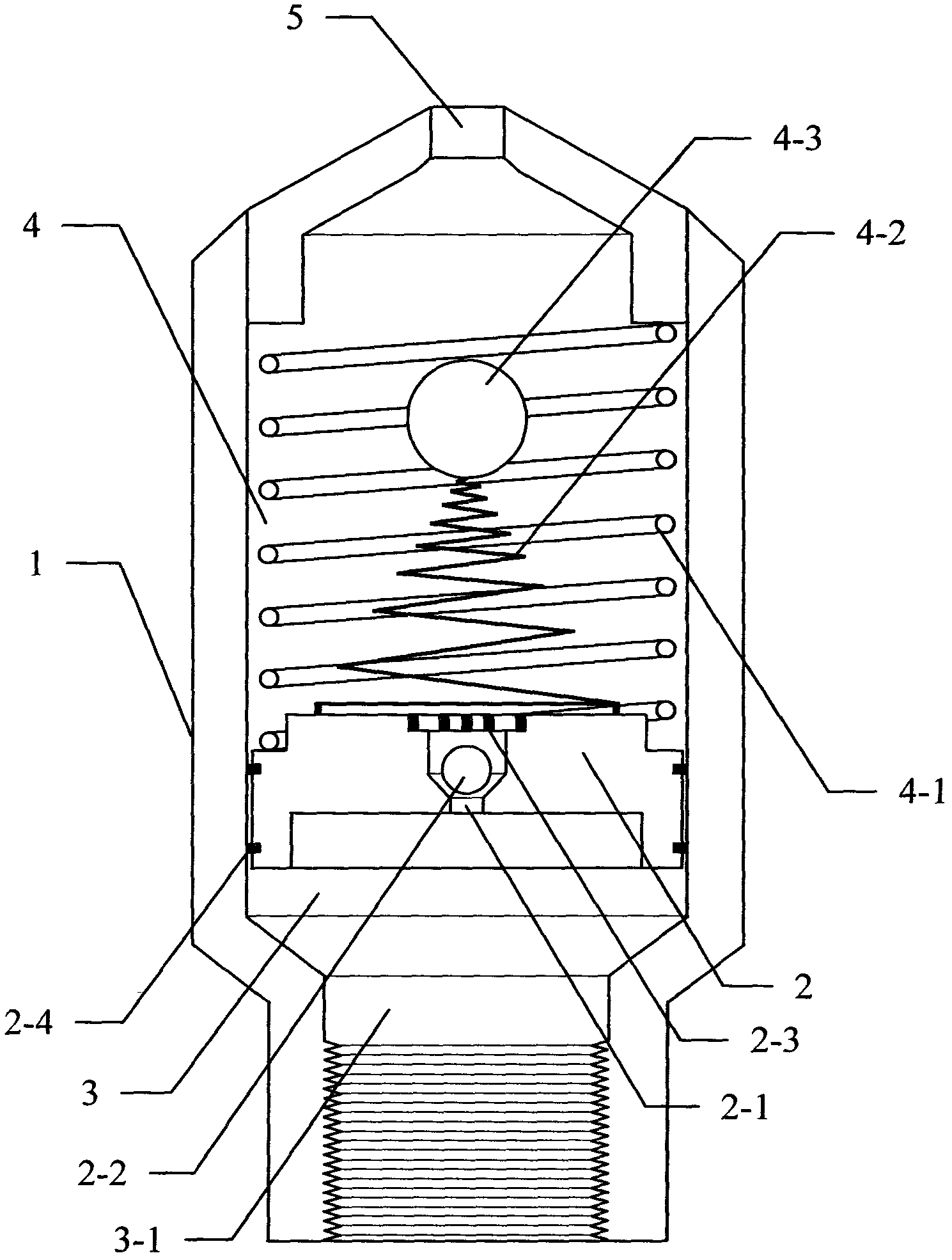
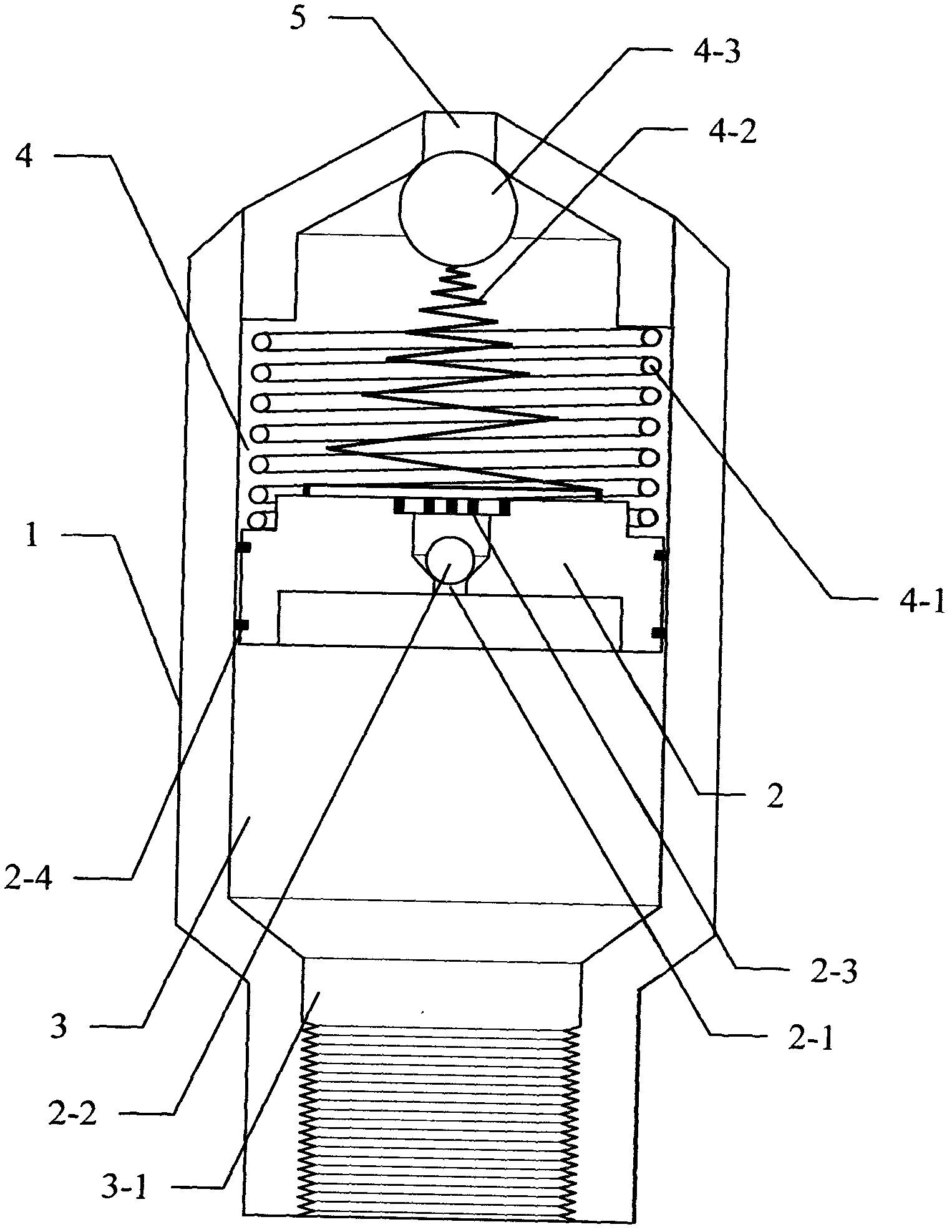
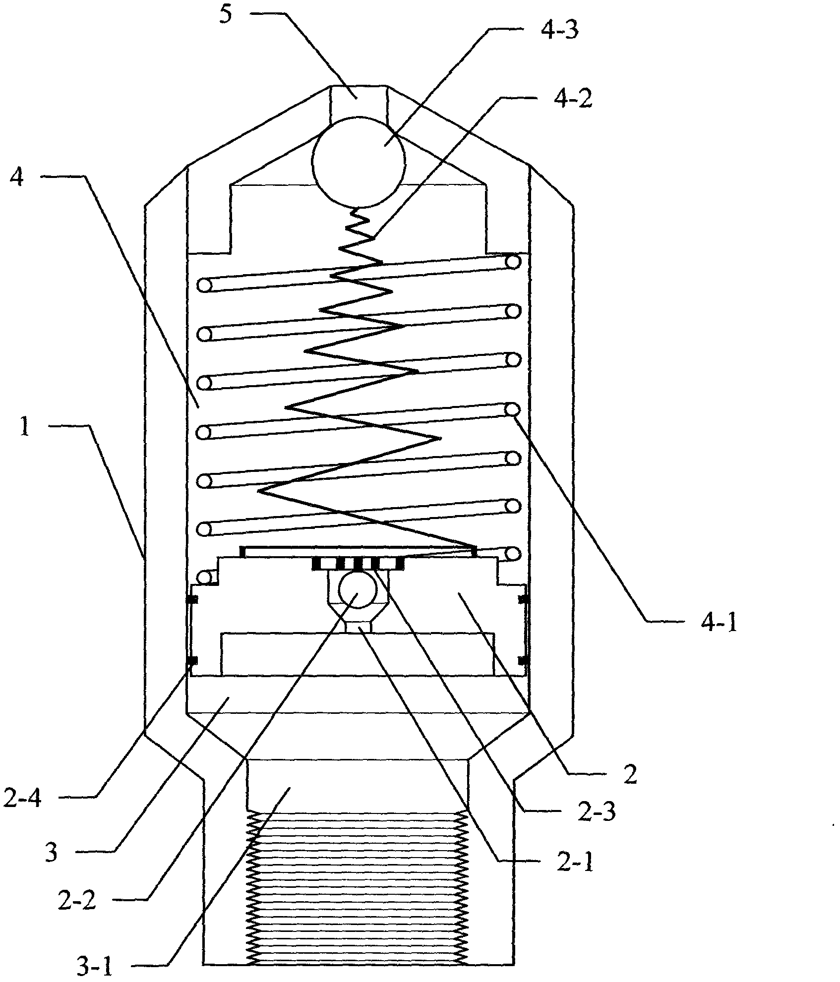
[0019] A fluid pulse jetting device, such as attached figure 1 , 2 , 3, including: a housing 1, a piston 2, the piston 2 divides the inner cavity of the housing 1 into a water inlet chamber 3 and a compression chamber 4, and the water inlet chamber 3 passes through the water inlet flow channel 3-1 and the water delivery pipe, etc. It is connected with a fluid pressure source such as a water pump. The piston 2 is provided with a compression chamber 4 water supply check valve and an elastic water stop ring 2-4. The elastic water stop ring 2-4 is fixed on the outside of the piston 2. The compression chamber 4 is provided with a Spring 4-1, tower spring 4-2, spherical elastic valve body 4-3, injection hole 5, compression spring 4-1 is set outside the tower spring 4-2, and one end of compression spring 4-1 is against the piston 2, the other end against the inner wall of the housing 1 close to the injection hole 5, the large end of the tower spring 4-2 is fixed on the piston 2, and...


PUM


Abstract

The invention relates to a fluid pulse spraying device, which comprises a shell and a piston. The piston enables a shell cavity to be separated into a water inlet cavity and a compression cavity, the water inlet cavity is connected with a fluid-power pressure source such as a water pump through a water inlet channel, a compression cavity water replenishing check valve and an elastic water stopping ring are arranged on the piston, a compression spring, a tower-shaped spring, a spheroidal elastic valve body and a spraying hole are arranged in the compression cavity, the compression spring is sleeved outside the tower-shaped spring, one end of the compression spring abuts against the piston, the other end of the compression spring abuts against the inner wall of the shell adjacent to the spraying hole, the large head end of the tower-shaped spring is fixed on the piston, the small head end of the tower-shaped spring is fixed on the spheroidal elastic valve body, and the curved surface ofan water inlet of the spraying hole is coincided with that of the spheroidal elastic valve body. The fluid pulse spraying device is simple in structure, free of electric drive and control, low in cost, convenient to use and particularly suitable for a pulse micro spray irrigation system, substitutes for a pulse solenoid valve deashing device of a bag-type dust collector, and can overcome the defect that a pilot hole is easy to block and be out of order, membrane opening time is long and membrane is short in service life.

Description


Claims


Application Information

Patent Timeline
Owner FARMLAND IRRIGATION RES INST CHINESE ACAD OF AGRI SCI
Why Eureka
Try Eureka