Welding gun adjusting device and automatic welding machine

A technology for adjusting devices and welding guns, applied in welding equipment, arc welding equipment, manufacturing tools, etc., can solve the problems of low degree of automation, difficult fine-tuning control, and affecting the accuracy of welding position adjustment, and achieve the effect of simple structure and low cost

Active Publication Date: 2012-02-22
ZOOMLION HEAVY IND CO LTD
View PDF8 Cites 37 Cited by
  • Summary
  • Abstract
  • Description
  • Claims
  • Application Information

AI Technical Summary

Problems solved by technology

In the welding position adjustment mechanism of this type of welding machine, such as the swing device or the cross slide, it is difficult to continuously and accurately adjust the welding position in the three-dimensional direction, and some welding position adjustment mechanisms indirectly adjust the welding position by adjusting the position of the welding head. Adjust the position of the welding torch, but this will easily affect the accuracy of the welding position adjustment and it is difficult to fine-tune the welding position. In addition, many welding position adjustment mechanisms have a low degree of automation and are mostly manual adjustments

Method used


Image

  • Welding gun adjusting device and automatic welding machine
  • Welding gun adjusting device and automatic welding machine
  • Welding gun adjusting device and automatic welding machine

Examples


Embodiment Construction

[0034] Specific embodiments of the present invention will be described in detail below in conjunction with the accompanying drawings. It should be understood that the specific embodiments described here are only used to illustrate and explain the present invention, and are not intended to limit the present invention.

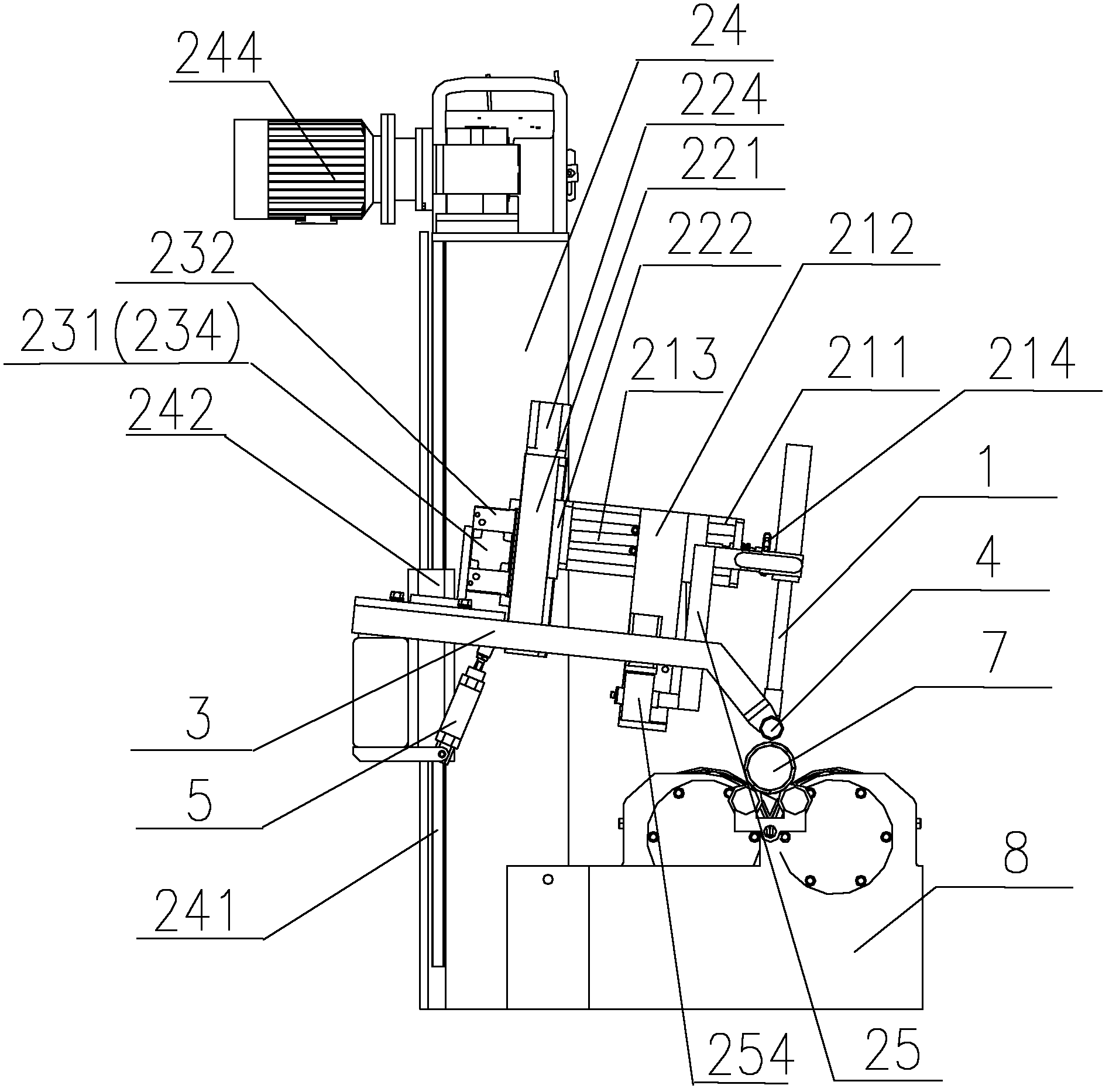
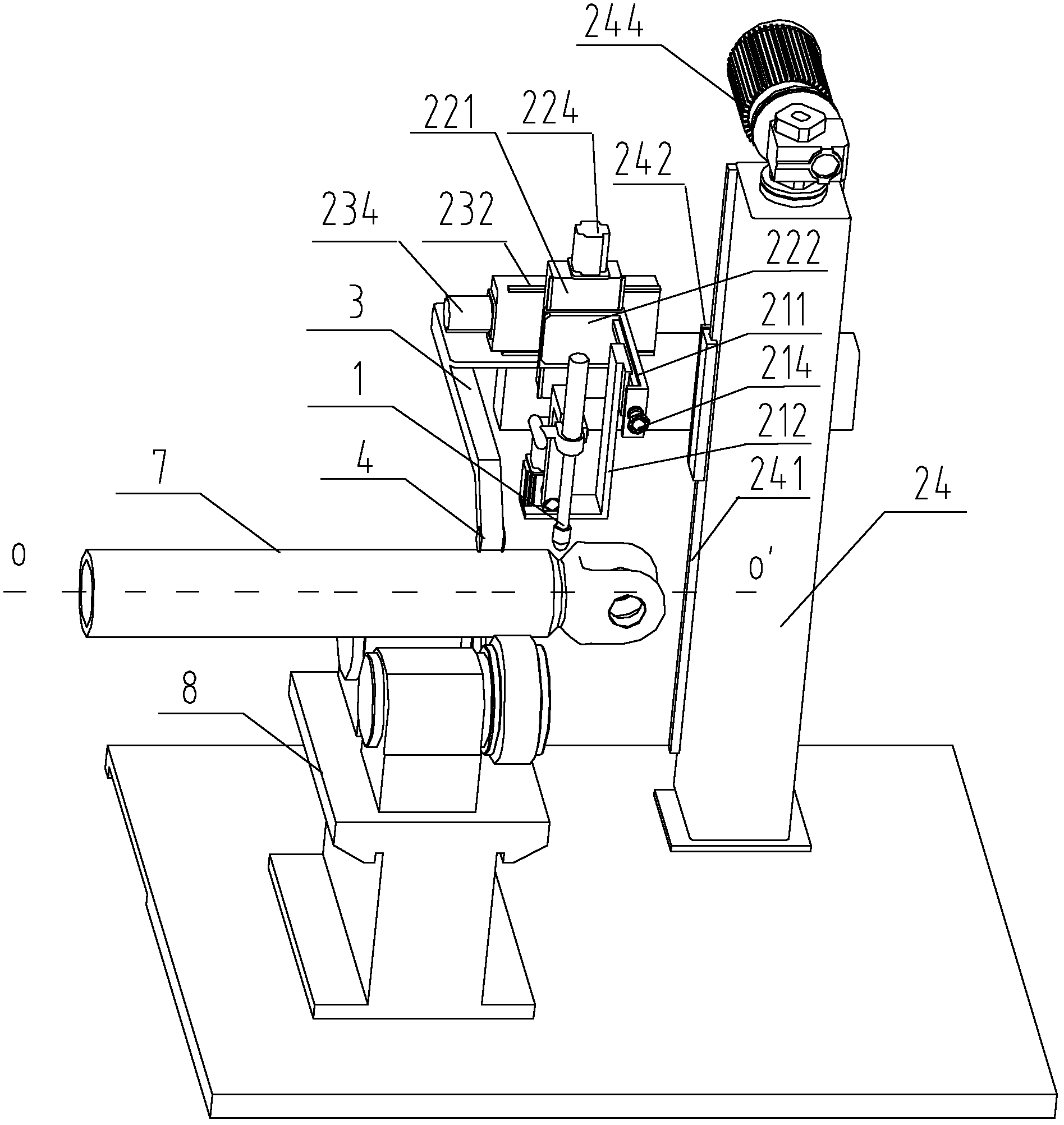
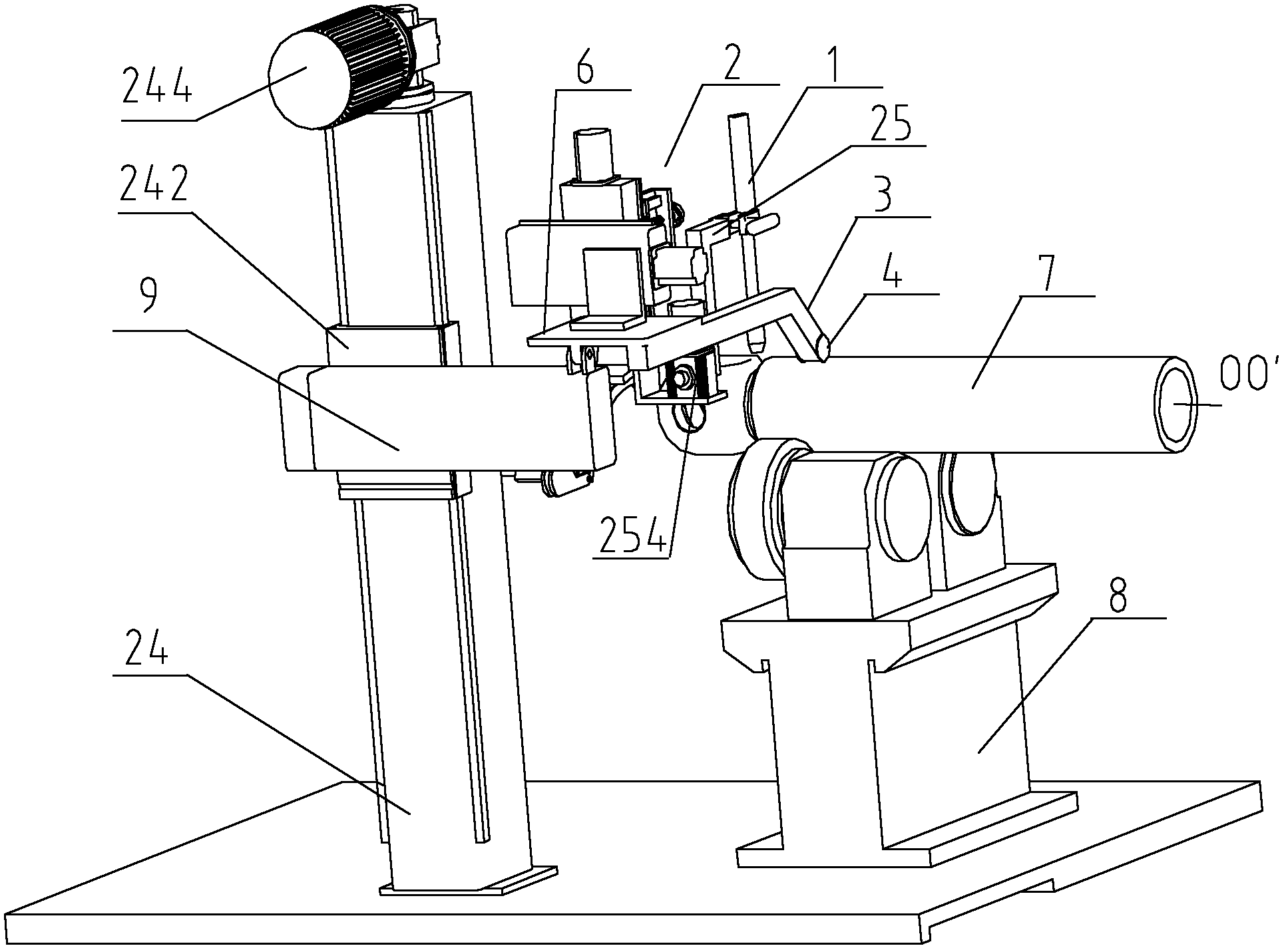
[0035] In the present invention, unless stated otherwise, the orientation words used such as "upper", "upper", "downward", "lower" and "vertical direction" are generally directed to the direction shown in the drawings. In terms of direction, or in terms of vertical or gravitational direction, the terms describe the mutual positional relationship of each component. The term "welding position" in this article refers to the position of the welding torch tip during welding, and "welding angle" refers to the inclination angle of the welding torch from the vertical direction (or horizontal direction) at the center of the welding point, that is, in swing welding The i...


PUM


Abstract

The invention relates to a welding gun adjusting device and an automatic welding gun with the same. The welding gun adjusting device comprises a welding head (2) and a welding gun (1) mounted on the welding head (2), wherein the welding head (2) can drive the welding gun (1) to realize position adjustment in three-dimensional direction. By adopting the welding gun adjusting device, the welding gun (1) can realize position adjustment in three-dimensional direction, and a welding angle adjusting mechanism can adjust the welding angle of the welding gun (1); and through adoption of a welding tracking device, corresponding position adjustment of the welding gun (1) can be taken along with a rolling pinch roller (4) so as to realize accurate positioning of the welding gun (1). The automatic welding machine provided by the invention can control the driving devices respectively through a welding control system so as to realize automatic welding.

Description

technical field [0001] The invention belongs to the field of welding equipment for pipe fittings, and in particular relates to a welding torch adjusting device and an automatic welding machine with the welding torch adjusting device. Background technique [0002] Truss structures are commonly used in public buildings such as large-span factories, exhibition halls, gymnasiums and bridges. Among them, some truss arms are formed by combined welding of circular tubular chords and ear hinges or supports at both ends, and the welds of the combined welding are circumferential welds. Due to the mechanical characteristics of the truss structure, the welds formed after welding on the truss arms have higher requirements in terms of connection strength, etc., so the circumferential welds are required to be strong and have a certain cross-sectional size, and considering the wall thickness and roundness of the round tube degree, the formed circumferential weld should have larger width an...

Claims


Application Information

Patent Timeline
Patent Type & Authority Applications(China)
IPC IPC(8): B23K9/127B23K9/022
Inventor 詹纯新刘权王莲芳易伟平钱世界
Owner ZOOMLION HEAVY IND CO LTD
Why Eureka
Try Eureka