
Sliding filling block for accurately positioning large part

A technology for precise positioning and large parts, applied in positioning devices, metal processing machinery parts, clamping, etc., can solve problems such as rack rebound, thin rack boards, scrapped parts, etc., to avoid distortion and reduce labor Strength and the effect of improving productivity

Active Publication Date: 2012-02-22
HEFEI RONGAN POWER MACHINERY
View PDF5 Cites 2 Cited by
  • Summary
  • Abstract
  • Description
  • Claims
  • Application Information

AI Technical Summary

Problems solved by technology

Such a high straightness error cannot be guaranteed due to the falling position of the crane hoist
It is quite troublesome to use manpower or a jack to push the frame of hundreds of tons on its side, and because the frame plate is thin, after pushing a certain strength on the side of the frame, when the jacking force is released, the machine will the rack bounces back
What is even more uncontrollable is that after the frame is pushed from the side, it is likely to be twisted. In this case, the subsequent machining will bring the risk of scrapping the parts

Method used


Image

  • Sliding filling block for accurately positioning large part
  • Sliding filling block for accurately positioning large part
  • Sliding filling block for accurately positioning large part

Examples


Embodiment Construction

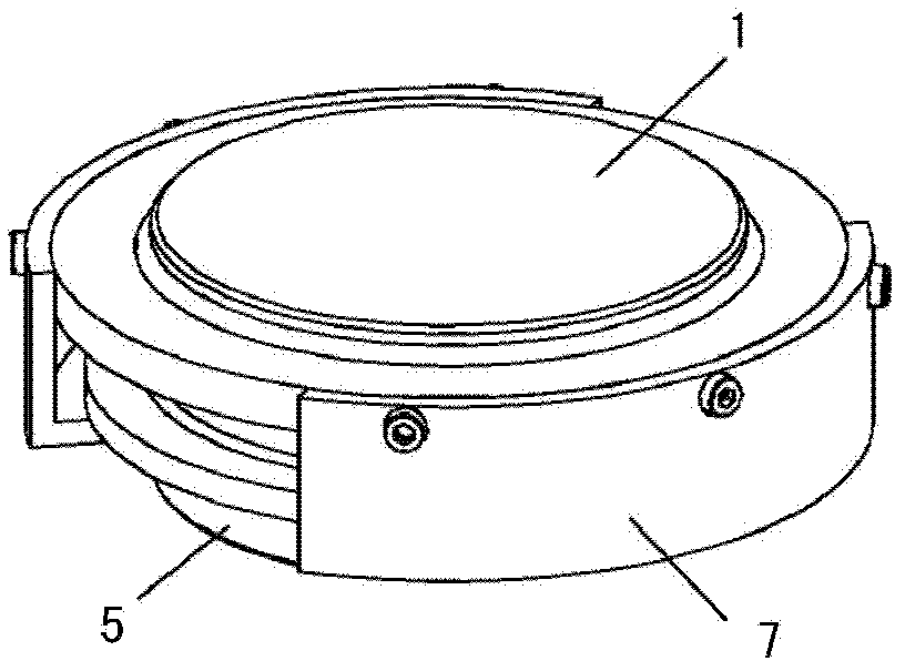
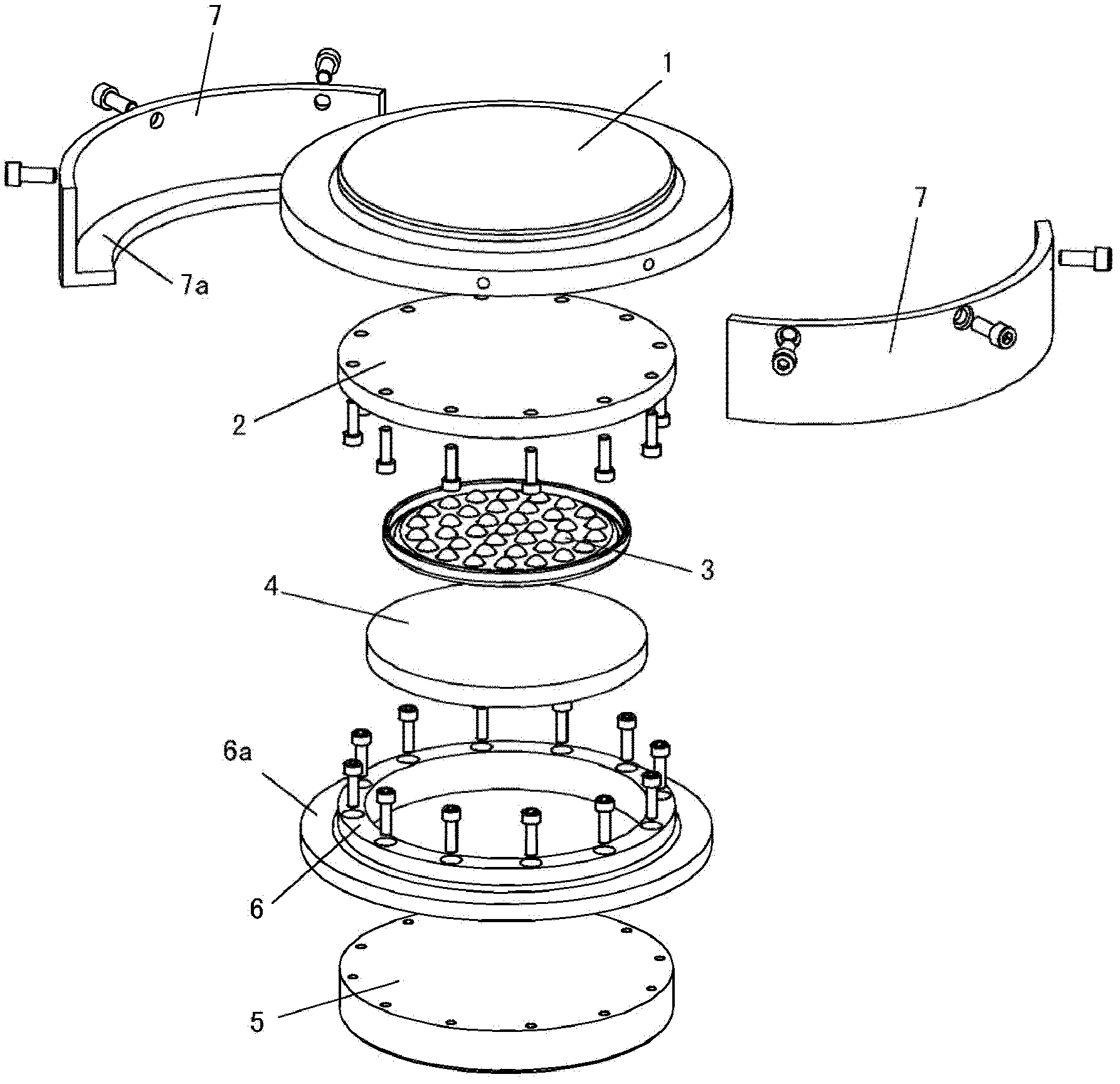
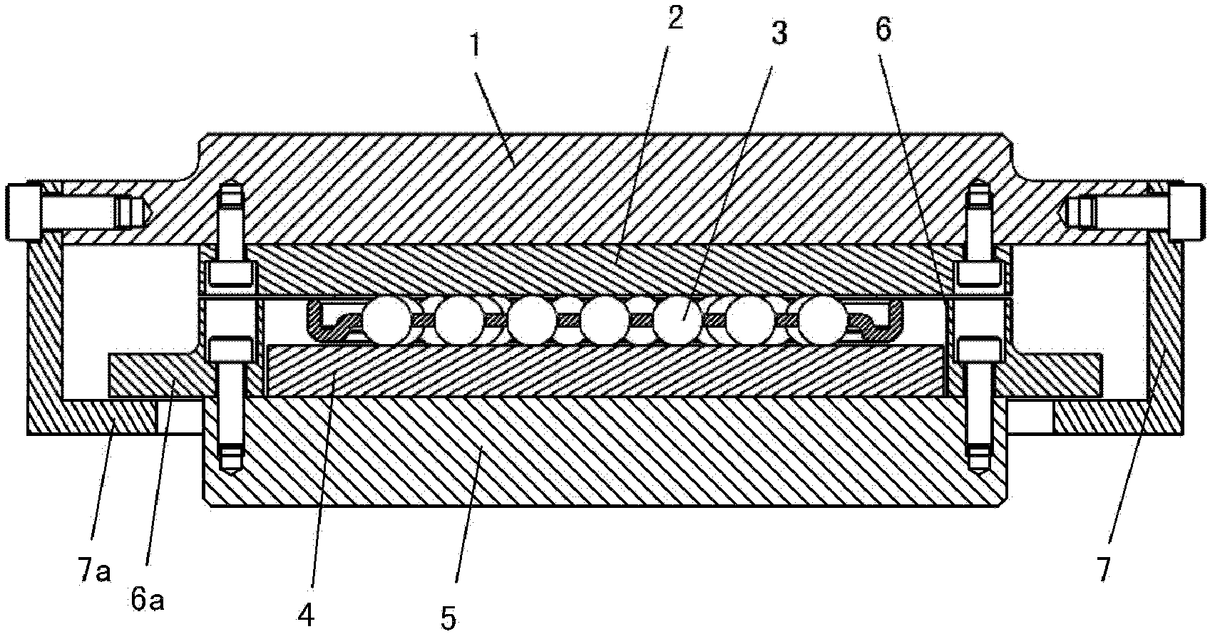
[0018] see figure 1 , figure 2 and image 3 In this embodiment, the structural form of the sliding block for precise positioning of large parts is that the chassis seat 5 and the intermediate ring sleeve 6 are fixedly connected to form a disc-shaped cavity, and the bottom plate 4 and the ball 3 are placed in the disc-shaped cavity. Placed on the upper plane of the bottom plate 4; the upper slide plate 2 supported by the ball 3 is fixedly connected with the top platform 1; the ring side plate 7 is fixed on the periphery of the top platform 1, and the ring side plate 7 forms a pair of chassis seats 5 and the middle. The annular position limiting of the ring sleeve 6, the ring side plate 7 can be made of two tile-shaped side plates, one left and one right symmetrically arranged. The ring side plate 7 not only provides the space for the free movement of the sliding pad, but also restricts this space to a certain extent.

[0019] In specific implementation, an inner flange 7a c...


PUM


Abstract

The invention discloses a sliding filling block for accurately positioning a large part. The sliding filling block is characterized in that: a disc-shaped cavity is formed by fixedly connecting a subbase and a middle ring sleeve into a whole; a bottom plate is arranged in the disc-shaped cavity; balls are arranged on the upper plane of the bottom plate; an upper sliding plate supported by the balls is fixedly connected with a top platform to form a whole; and the periphery of the top platform is fixedly connected with ring side plates which realize the annular limiting of the subbase and the middle ring sleeve. The sliding filling block is applied to positioning and correction in a preparation procedure before the machining of a large rack, avoids the distortion and deformation of the rack by decreasing a friction force between the rack and a hard filling block in a pushing process, and reliably ensures the product quality of subsequent machining.

Description

technical field [0001] The invention relates to an auxiliary positioning device, more specifically a sliding pad used for precise positioning and alignment in the preparation process for machining large parts. Background technique [0002] When using a CNC gantry milling machine to process large structural parts, such as large welded structural parts such as marine low-speed diesel engine parts and frames, because the weight of the frame parts of each model is hundreds of tons, and the structural parts are relatively thin, the frame machining When positioning and aligning the straightness of its center on the machine tool table before, there is a great tendency of distortion and deformation, and it is difficult to control it to complete subsequent machining in a free state. The larger the weight of the frame, the more difficult it is to adjust the quality of the straightness ensure. [0003] In the processing and manufacturing of large marine low-speed diesel engine parts, ...

Claims


Application Information

Patent Timeline
IPC IPC(8): B23Q3/10
Inventor 陈涛
Owner HEFEI RONGAN POWER MACHINERY
Learn More