Sludge desiccation system

A sludge drying and drying technology, applied in the direction of dewatering/drying/concentrating sludge treatment, etc., can solve the problems of drying efficiency, drying effect and stable operation of drying system, and the temperature cannot start auxiliary energy in time, etc. To achieve the effect of improving drying efficiency and drying effect, and increasing stability

Active Publication Date: 2012-02-22
安徽省通源环境节能股份有限公司
View PDF3 Cites 30 Cited by
  • Summary
  • Abstract
  • Description
  • Claims
  • Application Information

AI Technical Summary

Problems solved by technology

But there are certain problems in practical application, for example, when the temperature in the drying room drops due to insufficient solar energy supply, the

Method used


Image

  • Sludge desiccation system
  • Sludge desiccation system
  • Sludge desiccation system

Examples


Embodiment Construction

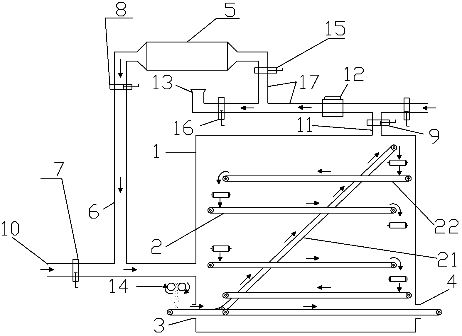
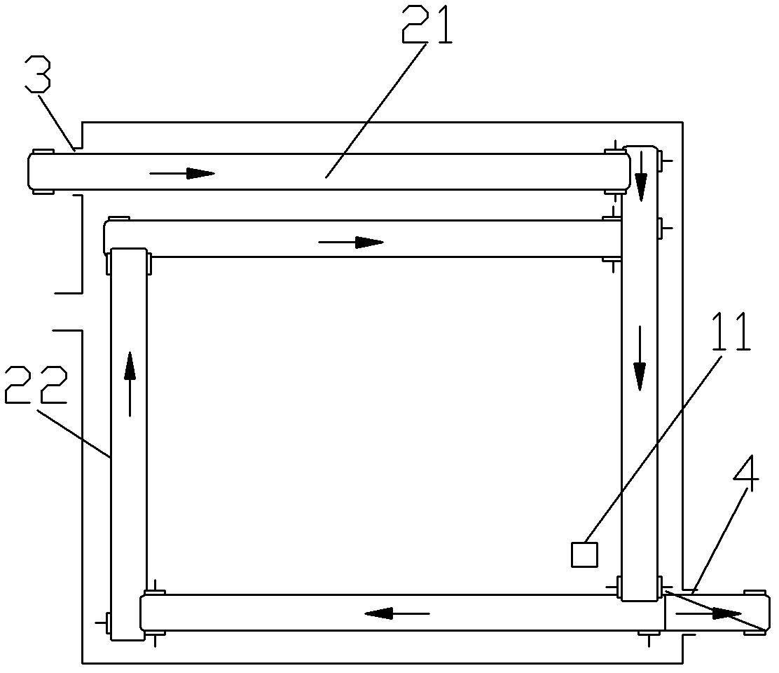
[0008] A sludge drying system, such as figure 1 , 2 As shown: the drying system includes a drying chamber 1, the drying chamber 1 communicates with the hot air pipeline 6 and the auxiliary heat source pipeline 10, and the drying chamber 1 includes a wet sludge inlet 3 and a dry sludge outlet 4 , moisture outlet 11, the drying chamber 1 also includes a sludge conveyor belt 2 located inside it, the hot air pipeline 6 communicates with the solar heat collector 5, and the solar heat collector 5 communicates with the solar heat collector 5 through the air duct 17 The fan 12 is connected, and the auxiliary heat source pipeline 10 is provided with a first temperature control valve 7 . The specific working state is: the wet sludge enters the drying chamber 1 through the wet sludge inlet 3, and runs on the conveyor belt 2, and is dried by hot air at the same time, until it is dried and discharged from the dry sludge outlet 4, and the evaporated water The air is discharged through the...


PUM


Abstract

The invention mainly aims to provide a sludge desiccation system. A technical scheme is as below: a sludge desiccation system comprises a drying chamber communicating with a hot-air pipeline and an auxiliary heat source pipeline; the drying chamber comprises a wet sludge inlet, a dry sludge outlet, a moisture exhaust and a sludge conveyor belt inside the drying chamber; the hot-air pipeline is communicating with a solar heat collector, which is communicating with a blower fan through an air channel; and the auxiliary heat source pipeline is provided with a temperature control valve. The desiccation system not only utilizes solar energy and heat tail gas or steam discharged by a factory effectively to enhance desiccation efficiency and desiccation effect, but also enhances operating stability of the desiccation system.

Description

technical field [0001] The invention relates to the field of solid waste treatment, in particular to a sludge drying system. Background technique [0002] At present, the drying of cyanobacteria mud / sludge uses solar energy, a new green energy source, but the application of solar drying technology has the problem of unstable use of solar energy, such as the intensity of solar energy and the change of seasons, the alternation of daylight, the weather, etc. The condition is directly related, so it directly affects the stable operation of the cyanobacteria mud / sludge drying system. At present, the main method to solve this problem is to use auxiliary energy, that is, when the heat provided by solar energy is not enough to realize the drying of cyanobacteria mud / sludge, the auxiliary energy is provided to the drying room. At present, most of this auxiliary energy is discharged from the factory hot exhaust or steam. However, there are certain problems in practical application, ...

Claims


Application Information

Patent Timeline
IPC IPC(8): C02F11/12
Inventor 吴克金杰王学军俞志敏董强刘斌
Owner 安徽省通源环境节能股份有限公司
Why Eureka
Try Eureka