Square extending type cloth conveying tube

A square cloth feeding technology, applied in the field of dyeing and finishing machinery, can solve the problems of low passing speed, slow water circulation speed, slow water cloth separation, etc., and achieve the effect of lowering the water level of the machine, reducing the dyeing cost, and reducing the dyeing bath ratio

Active Publication Date: 2013-04-24
GUANGDONG SANJI KLANGZ MECHANICAL TECH CO LTD
View PDF6 Cites 0 Cited by
  • Summary
  • Abstract
  • Description
  • Claims
  • Application Information

AI Technical Summary

Problems solved by technology

[0006] 3. From the front nozzle, the circular cloth feeding pipe to the rear left and right buckets, there are all circular passages, and the cloth is very entangled in the passage, causing a large number of creases and easily causing dead marks
[0007] 4. The outlet of the rear left and right buckets is downward, and the dye liquor and cloth pieces fall vertically, so the dye liquor must fall completely before passing through the rear water separation plate. Larger volume, higher liquor ratio

Method used


Image

  • Square extending type cloth conveying tube
  • Square extending type cloth conveying tube

Examples


Embodiment Construction

[0027] The present invention will be further described below in conjunction with drawings and embodiments.

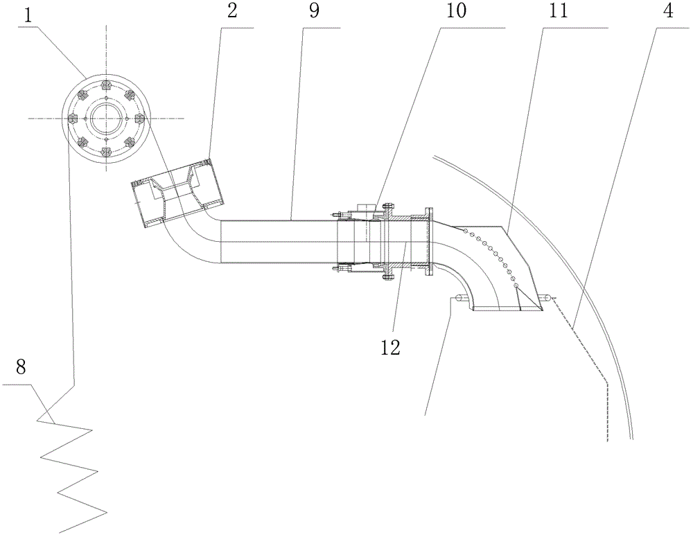
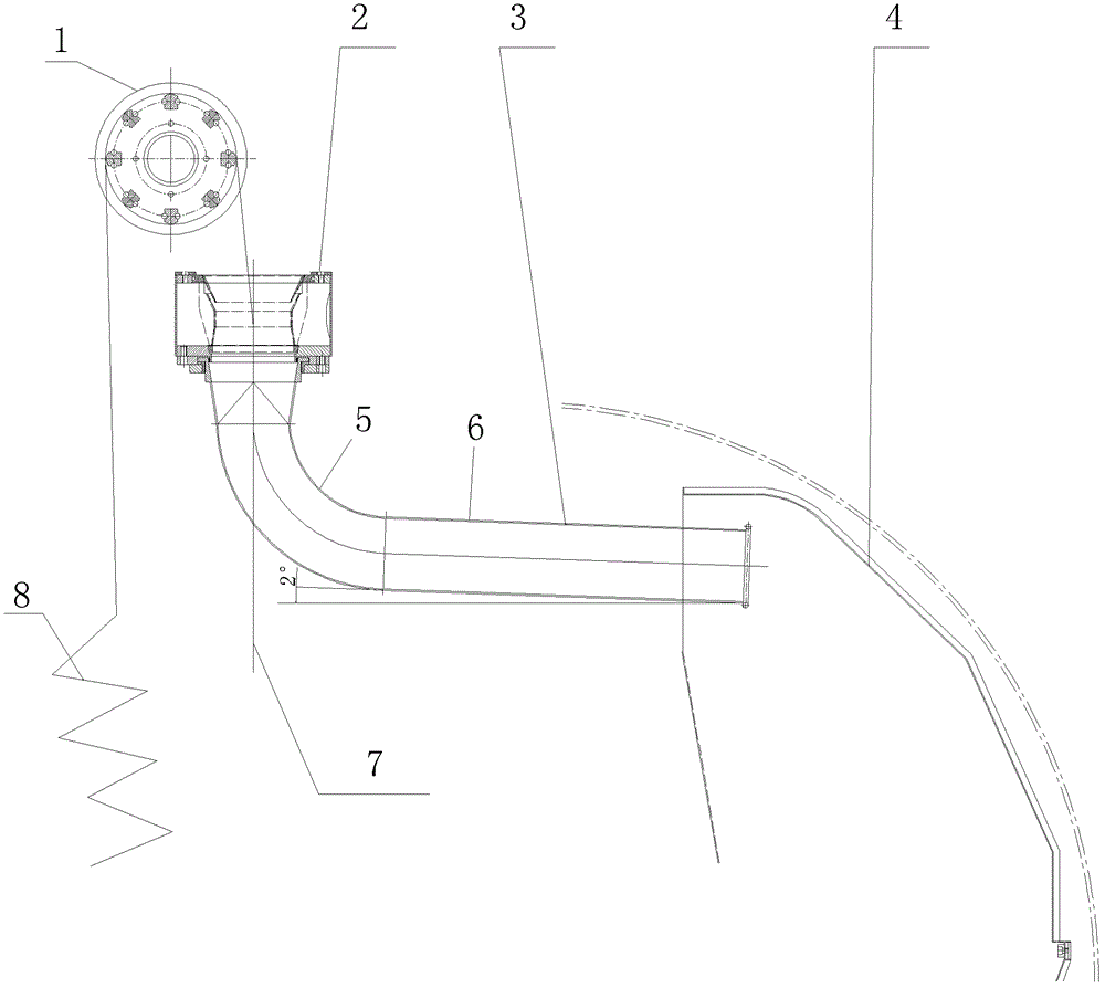
[0028] like figure 2 The UF and UFH machines shown are square stretch-type cloth feeding pipes, including a lifting roller, a front nozzle, a square cloth feeding pipe and a rear water diversion plate. The lifting roller is located above the front nozzle side, and the front nozzle is placed horizontally. section and straight section, the curved section is swingably connected to the lower end of the front nozzle, the straight section is placed obliquely, and the outlet of the square distribution pipe faces the rear water diversion plate.

[0029] The swing axis of the square feeding pipe is the central axis of the front nozzle. The swing angle of the square feeding pipe is 10°. The straight section forms an angle of 2° with the horizontal plane. The entrance at the upper end of the curved section is a structure below the upper circle. One side of the rear water dive...


PUM


Abstract

The invention discloses a square extending type cloth conveying tube which comprises an elevating roller, a front nozzle, a square cloth conveying tube and a rear water separating plate, wherein the elevating roller is located above the side of the front nozzle; the front nozzle is horizontally placed; the square cloth conveying tube comprises a bending segment and a straight segment; the bendingsegment can be connected to the lower end of the front nozzle in a swing mode; the straight segment is placed in an inclined mode; and an outlet of the square cloth conveying tube faces the rear water separating plate. The square extending type cloth conveying tube has the advantages of reasonable structure, low bath ratio, no knotting and less kink marks and crease marks.

Description

technical field [0001] The field of the invention: dyeing and finishing machinery, in particular to a square stretch-type cloth feeding pipe. Background technique [0002] The traditional feeding pipe structure such as figure 1 Shown: including the lifting roller, front nozzle, circular cloth feeding pipe, rear nozzle, rear distribution bucket and rear water diversion plate, the lifting roller is located above the front nozzle side, the front nozzle is placed obliquely, and the circular cloth feeding pipe includes the curved section and The straight section and the curved section are fixedly connected to the lower end of the front nozzle. The straight section is placed horizontally. The straight section is connected to the rear nozzle. The rear swing bucket is connected to the rear nozzle. Exit down. [0003] Above-mentioned structure has following defect: [0004] 1. Because the circular cloth feeding pipe has a turning point and the rear left and right bucket has a turn...

Claims


Application Information

Patent Timeline
Patent Type & Authority Patents(China)
IPC IPC(8): D06B23/00D06B1/02
CPCD06B3/28
Inventor 郑永忠陈红军
Owner GUANGDONG SANJI KLANGZ MECHANICAL TECH CO LTD
Why Eureka
Try Eureka