Improved method for installing reinforcement cage in beam column joint zone of reinforced concrete frame structure

A technology of reinforced skeleton and column joints, which is applied in the direction of building construction, construction, and building material processing, etc., and can solve problems such as difficult operation, unawareness, and difficult operation

Active Publication Date: 2012-02-22
INSTALLATION BRANCH WEIHAI CONSTR GRP CO LTD
View PDF3 Cites 22 Cited by
  • Summary
  • Abstract
  • Description
  • Claims
  • Application Information

AI Technical Summary

Problems solved by technology

[0004] The reason why this kind of problem occurs is that the construction personnel do not operate in a standardized manner, do not realize it, and do not pay attention to it. The more important reason is that the installation of the column stirrup at the joint is complicated and difficult to operate. The traditional installation method is difficult to meet the design requirements. Design anti-seismic effect
The traditional method of installing the reinforcement skeleton at the joints of beams and columns is as follows: after the formwork of the beam-column-slab member is supported on site, the column stirrups are bound on the column longitudinal reinforcement (insertion reinforcement), and then a column stirrup is placed directly above the beam formwork groove. In the wooden square, the beam longitudinal reinforcement passes through the column longitudinal reinforcement and column stirrup (this operation is very difficult and time-consuming

Method used


Image

  • Improved method for installing reinforcement cage in beam column joint zone of reinforced concrete frame structure
  • Improved method for installing reinforcement cage in beam column joint zone of reinforced concrete frame structure
  • Improved method for installing reinforcement cage in beam column joint zone of reinforced concrete frame structure

Examples


Embodiment Construction

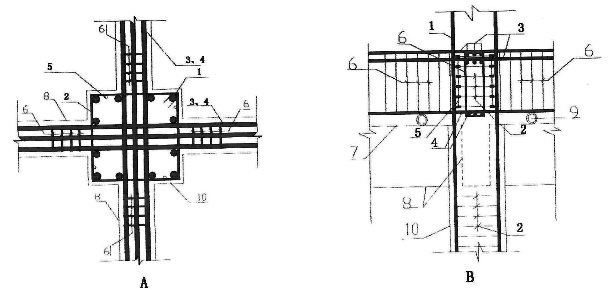
[0013] 1. Make the column stirrup limit mold rod, the structure is as follows Figure 4 Middle B picture. The length of the reinforcing bar head 5 on the limiting mold bar is equal to the height of the larger beam section at the core area of ​​the beam-column joint, the diameter of the short reinforcing bar section 11 is the diameter of the column stirrup, and the length 13 is 2 to 3 cm, and the distance 12 between a pair of short reinforcing bar sections 11 is the column Stirrup diameter, the distance 14 between two pairs is the column stirrup spacing; The manufacturing material of mold bar is the steel bar waste of construction site, can adopt Φ8, Φ10 steel bar to get final product. The specific implementation is as follows: ① Firstly, the mold plate made by prefabricating the limit mold bar with cement mortar (with steel wire mesh inside) is used in the corner of the on-site steel bar processing workshop (details Figure 5 A picture in middle) or a mold that is processed i...


PUM


Abstract

The invention discloses an improved method for installing a reinforcement cage in the beam column joint zone of a reinforced concrete frame structure, which belongs to the building and the structure of the reinforced concrete frame structure in the civil engineering field. The method aims to overcome the problems brought by the traditional installing method, can guarantee the installing quality of the reinforcement cage at the positions of the nodes of beams and columns and creates great convenience for operation. In the detail drawing 3, erecting a bracket above a beam template groove; the longitudinal reinforcements of the beams are interspersed in the longitudinal tendons of the columns and are arranged on the bracket; core zone column stirrups are arranged at the positions of the longitudinal tendons of the columns and between the upper longitudinal tendons and the lower longitudinal tendons of the beams; the longitudinal reinforcements of the beams are fixed by being bonded with the stirrups of the beams; the stirrups of the columns are fixed by bonded with stirrup spacing tringles (B in the drawing 4) to form a reinforcement cage in the beam column joint zone, which is temporarily arranged exactly above the beam column joint zone and the beam template groove and is not bonded with the longitudinal tendons of the columns; finally, the beam reinforcement cage and a column stirrup cage integrally slide into the beam template groove and the beam column joint core zone along the longitudinal tendons of the columns; and therefore, the final position of the reinforcement cage in the beam column joint zone is realized.

Description

Technical field: [0001] Buildings and structures belonging to reinforced concrete frame structures in the field of civil engineering, repeatedly researching and summarizing the method of installing reinforced skeletons for important parts of engineering earthquake resistance (beam-column nodes). Background technique: [0002] In recent years, there have been many destructive earthquakes, which have caused huge losses to human life and property. People's awareness of engineering earthquake resistance and earthquake resistance has been continuously strengthened. A series of anti-seismic measures (such as shock absorption and anti-seismic measures, etc.) have been adopted from the planning and design of buildings. The design of reinforced concrete frame structures has now formed relatively mature anti-seismic and anti-seismic design concepts such as: strong nodes and weak members, strong columns and weak beams, Strong shear weak bend and so on. The dense setting of column sti...

Claims


Application Information

Patent Timeline
IPC IPC(8): E04G21/12E04B1/41E04B1/58
Inventor 宋瑞杰高中勤张葆华朱明清
Owner INSTALLATION BRANCH WEIHAI CONSTR GRP CO LTD
Why Eureka
Try Eureka