Driven gear device for motorcycle engine

A technology of driven gear and engine, applied in transmission parts, transmission control, belt/chain/gear, etc., can solve the problems of engine stall, impact of engine parts, danger of separation of people and vehicles, etc.

Active Publication Date: 2015-02-04
ZHEJIANG CFMOTO POWER CO LTD
View PDF6 Cites 0 Cited by
  • Summary
  • Abstract
  • Description
  • Claims
  • Application Information

AI Technical Summary

Problems solved by technology

The driven gear on the transmission sub-shaft of the traditional transmission device can be used for each gear when the motorcycle starts to adjust the gears. The flameout will cause a large impact on the engine parts, and it may also cause the motorcycle to accelerate suddenly, and the driver is not mentally prepared to cause the danger of separation of the man and the vehicle

Method used


Image

  • Driven gear device for motorcycle engine
  • Driven gear device for motorcycle engine
  • Driven gear device for motorcycle engine

Examples


Embodiment Construction

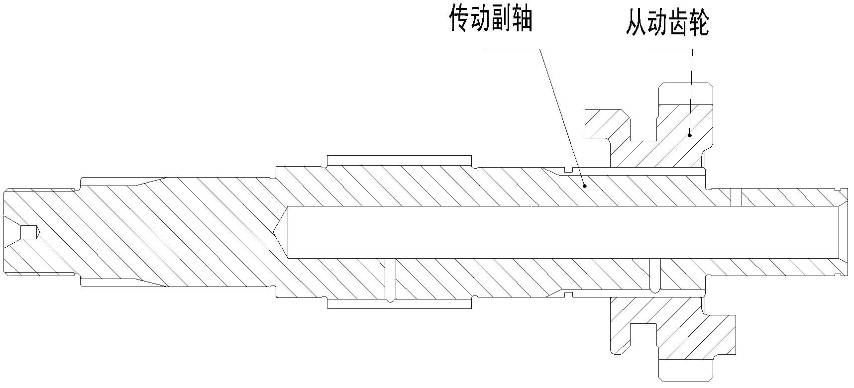
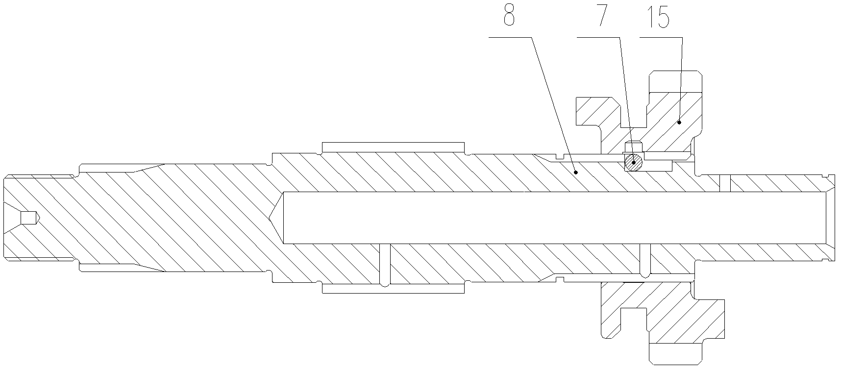
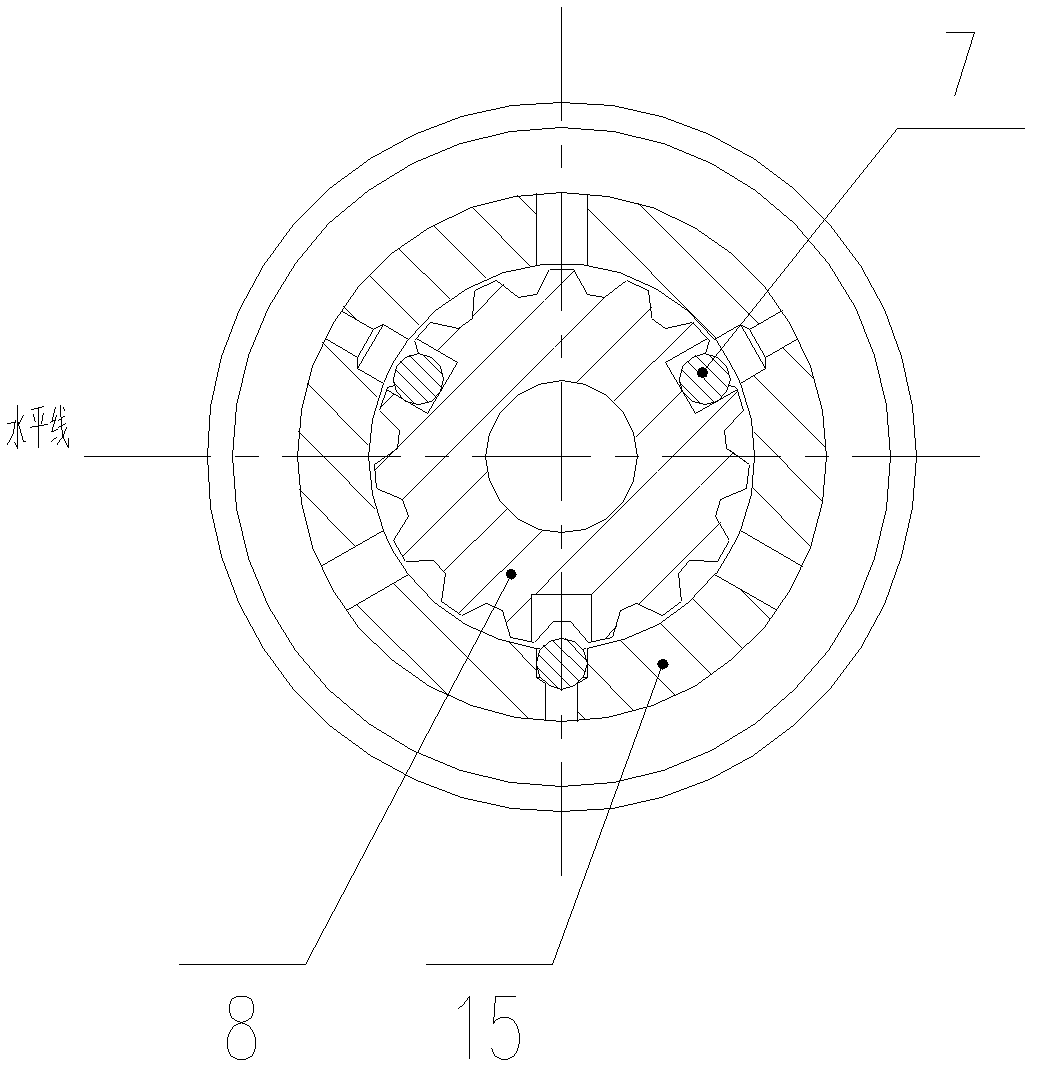
[0016] The embodiment of the present invention transforms the traditional driven gear device. An inner spline is arranged on the inner surface of the driven gear, and a hole groove is arranged on the inner spline, and a steel ball is installed in the hole groove. The diameter of the steel ball is smaller than the depth of the hole groove, and the corresponding The transmission sub-shaft is provided with an external spline and a chute, the chute corresponds to the position of the hole of the driven gear, and the depth of the chute is smaller than the diameter of the steel ball. When the driven gear device starts the motorcycle, the steel ball in the hole groove above the horizontal line will fall into the chute of the transmission countershaft due to its own gravity, so that the sliding of the driven gear is limited, and the motorcycle cannot be hung into the secondary shaft. The gears above and above can only be started in one gear, which avoids the danger of separation of peop...


PUM


Abstract

The embodiment of the invention provides a driven gear device for a motorcycle engine. The device comprises a driven gear and a transmission auxiliary shaft, wherein the driven gear is arranged on the transmission auxiliary shaft; an internal spline is arranged on the internal surface of the driven gear and is meshed with an external spline of the transmission auxiliary shaft; the internal spline of the driven gear is provided with at least three hole grooves; steel balls are arranged in the hole grooves; the diameter of the steel balls is smaller than the depth of the hole grooves; the transmission auxiliary shaft is provided with the external spline and chutes; the chutes correspond to the hole grooves of the driven gear; and the depth of the chutes is smaller than the diameter of the steel balls. The driven gear device in the embodiment of the invention can ensure the safety of a driver by changing the positions of the steel balls.

Description

technical field [0001] The invention relates to the technical field of motorcycle transmission systems, in particular to a driven gear device for a motorcycle engine. Background technique [0002] Motorcycle speed change is achieved by adjusting the gear position on the transmission device. One end (input end) of the transmission device meshes with the output gear on the crankshaft of the engine through the large gear of the clutch, and the other end (output end) through the output sprocket, chain Attaches to the wheel of the motorcycle. There are multiple pairs of gears with different numbers of teeth inside the speed change device. When shifting, the gear ratio corresponding to different gear positions is used to realize the speed change. Different gear positions have different gear reduction ratios. The speed change device of the motorcycle on the market usually adopts the speed change mode of "two-axis five-speed or six-speed". The transmission device of this mode incl...

Claims


Application Information

Patent Timeline
Patent Type & Authority Patents(China)
IPC IPC(8): F16H63/34F16H57/00
Inventor 赖国贵袁章平党向元杨志球张淑坤
Owner ZHEJIANG CFMOTO POWER CO LTD
Why Eureka
Try Eureka