
Register of direct-reading water gauge

A counter and direct-reading technology, which is applied in the direction of instruments, volume metering, and measuring devices, can solve the problems of many code reading interference factors, multiple detection devices, and complicated coding, so as to reduce the waste of manpower and material resources and ensure The effect of practicality and high reliability

Inactive Publication Date: 2012-02-22
广东鼎鸿智联科技有限公司
View PDF9 Cites 23 Cited by
  • Summary
  • Abstract
  • Description
  • Claims
  • Application Information

AI Technical Summary

Problems solved by technology

[0004] The Chinese patent application number is CN200910010368.5, which discloses a remote meter two-dimensional coded digital wheel and its integrated sensor code reading device, which fundamentally solves the existing remote meter digital wheel carrying "angle one-dimensional code" information The code reading device uses many detection devices, complex coding, and many code-reading interference factors. It includes the coding strip arranged on the outer circumferential surface of the black substrate of the coding digital wheel. The technical points are: the coding strip is set A light-colored ten-segment equal difference step width code or a ten-segment odd-even step width code has a width step code bar, and the corresponding width step code bar on the outer peripheral surface of the code number wheel is evenly arranged in red numbers 0 to 9, and its code reading device reads The integrated width sensor parallel to the digital wheel shaft is packaged on the code reading and decoding circuit board of the coder, and multiple sensor segments are set on the working surface of the integrated width sensor corresponding to the width ladder coding strip
[0013] The disadvantages of the inventor's patent application above are as follows: since the wheel-type electronic reading device is designed according to the traditional water meter and does not change the size of the traditional water meter, it is difficult to install the sensor in the inner shell of the water meter. Due to volume limitations, only one sensor can be installed, and sometimes there are errors in the readings during operation. In addition, the circuit board is generally installed between the digital wheels, and the layout is too small to cause problems.

Method used


Image

  • Register of direct-reading water gauge
  • Register of direct-reading water gauge
  • Register of direct-reading water gauge

Examples


Embodiment Construction

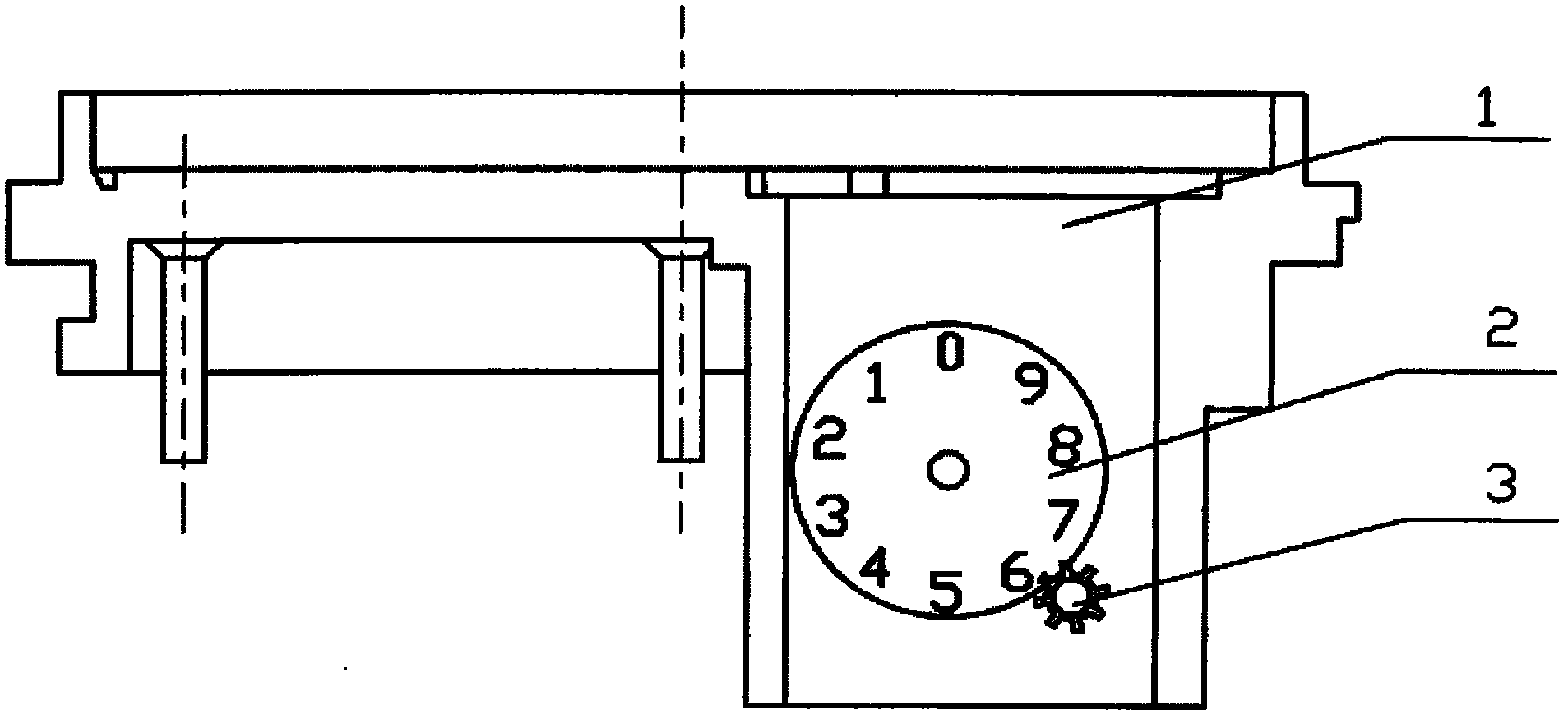
[0030] Such as figure 1As shown, the traditional digital wheel water meter structure includes a housing 1, a digital wheel 2 and a carry wheel 3. The housing 1 is made of transparent material, and the carry wheel 3 can be four or eight wheels, and the carry wheel is installed On the bottom or side of the number wheel.

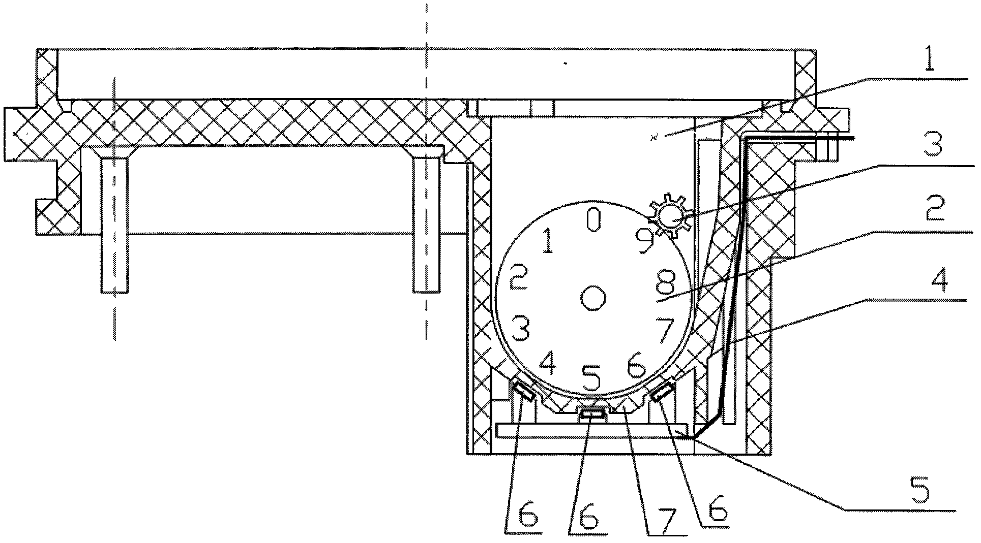
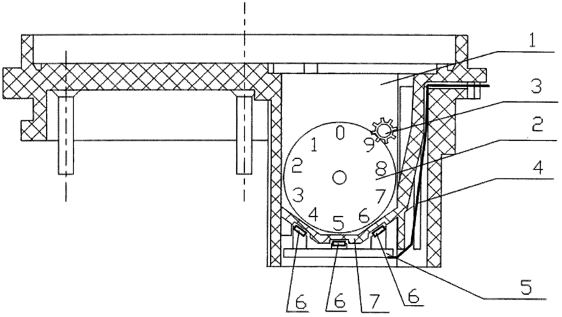
[0031] Such as figure 2 As shown, the direct-reading water meter counter of the present invention heightens and widens the water meter counter housing 2, and each number of the number wheel 2 is inlaid or coated with materials corresponding to the sensor, such as photoelectric materials and ferromagnetic materials. etc., install 2-3 sensors 6 in the lower part of the housing 1 to identify the digital wheel 2, the carry wheel 3 is installed on the side of the digital wheel 2, the upper right corner, the circuit board 5 is installed at the bottom of the housing, and the digital wheel in the housing A transparent thin polyester isolation plate 7 is set between ...


PUM


Abstract

The invention provides a register of a direct-reading water gauge. The register comprises a digital wheel, a shell and a carry wheel; the carry wheel is arranged at the bottom or side of the digital wheel; each number of the digital wheel is correspondingly embedded or painted with materials corresponding to sensors; 2-3 sensors used for identifying the digital wheel are arranged at the lower part of the shell; a circuit board is arranged at the bottom of the shell and outputs a signal through a lead. The register of the direct-reading water gauge is improved based on the traditional digital wheel water gauge; therefore, the register has the advantages of low cost, accurate sensing data, reliable performance and low running fault.

Description

technical field [0001] The invention relates to a digital wheel-type intelligent water meter, in particular to a direct-reading water meter counter. Background technique [0002] In order to change the situation that traditional water meters need to be read at home, people have designed many water meters that can transmit signals remotely. There are many water meters or sensors for long-distance signal transmission disclosed in Chinese patents, and the forms and structures are also different. After retrieval, some excerpts are taken as Review the background technology: [0003] Chinese Patent Application No. 200620116636 discloses a liquid-sealed passive digital humidity-transmitting water meter, including: a meter body, a digital wheel box, a sensor assembly, a control and digital signal processing circuit board, signal wires, and lead-out electrodes. The control and digital signal processing circuit board in the liquid-sealed passive digital transmission wet water meter i...

Claims


Application Information

Patent Timeline
IPC IPC(8): G01F15/07
Inventor 黄华
Owner 广东鼎鸿智联科技有限公司
Learn More