High-efficiency fluid electromagnetic magnetizer

A magnetizing device and fluid technology, which is applied to circuits, magnetic objects, electrical components, etc., can solve the problems of shortening the effective time of fluid particles, inconvenient use by users, inconvenient maintenance, and increased device manufacturing costs, and achieves extended effective time. Magnetization effect boost effect

Inactive Publication Date: 2012-02-22
宜兴市氿润环保研究所有限公司
View PDF3 Cites 3 Cited by
  • Summary
  • Abstract
  • Description
  • Claims
  • Application Information

AI Technical Summary

Problems solved by technology

Theoretically, the direction of fluid travel perpendicular to the direction of the magnetic field can receive the best magnetization effect, but in general, the volume of the source magnet used for magnetization cannot be made very large, so the fluid particles traveling at a certain flow rate flow in the same magnetic field. The elapsed time is relatively short. If there is a long time requirement for magnetization, there will be problems. Multi-point magnetization or segmental magnetization will cause turbulence, time lag and discontinuity caused by fluid in the container or pipeline. Factors lead to a serious decline in the magnetization effect, and at the same time will greatly increase the manufacturing cost of the device, and also bring inconvenience to the user's use and maintenance
In addition, it is impossible to make the magnetic field strength infinite for the source magnet, and the improvement of the magnetization effect by simply increasing the magnetic field strength generated by the source magnet is restricted by factors such as technology and price requirements.
For most fluids, increasing the speed at which the fluid cuts the magnetic field lines in the magnetic field is beneficial to the improvement of the magnetization effect, but increasing the flow rate will shorten the effective time for the fluid particles to flow through the magnetic field, which is a pair of prominent contradictions

Method used


Image

  • High-efficiency fluid electromagnetic magnetizer
  • High-efficiency fluid electromagnetic magnetizer
  • High-efficiency fluid electromagnetic magnetizer

Examples


Embodiment Construction

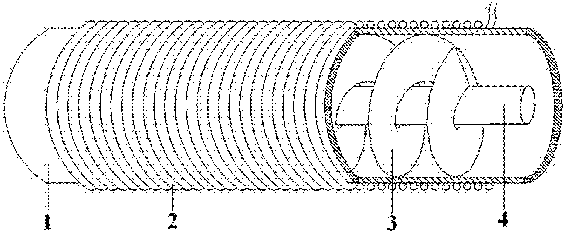
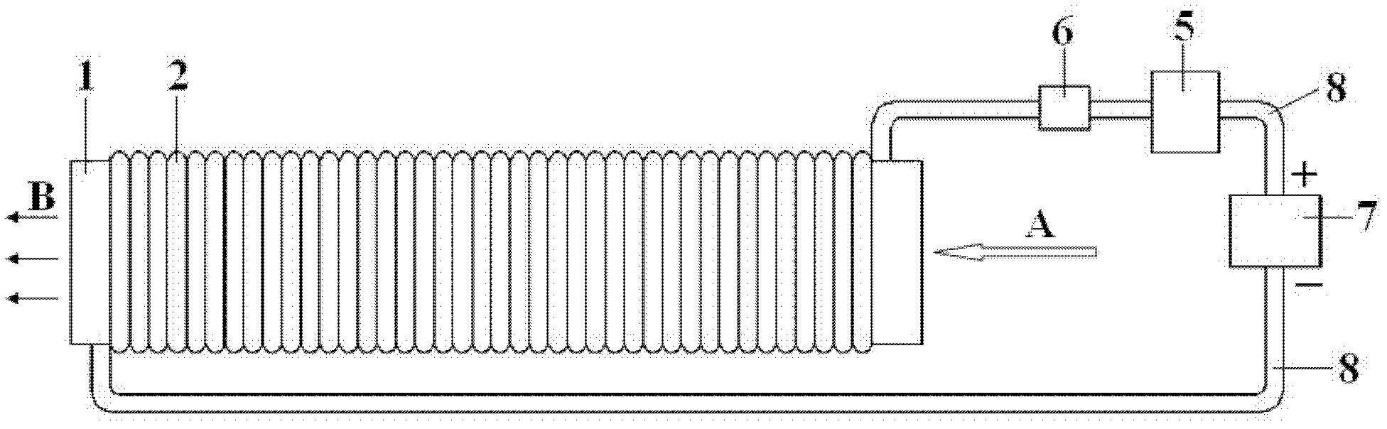
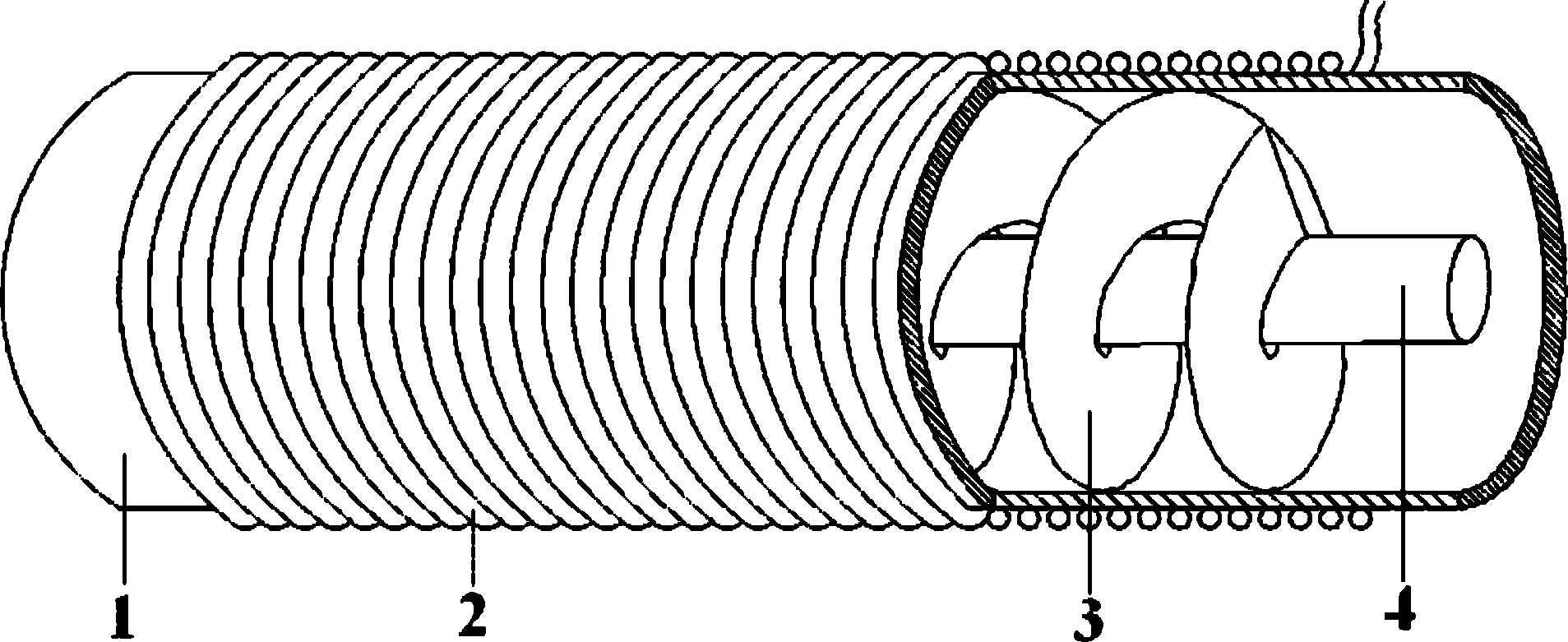
[0017] Such as figure 1 The high-efficiency fluid electromagnetic magnetization device shown includes a tube body 1, an electromagnetic winding 2, a flow guide screw 3 and a tube core 4. The outer circumference of the tube body 1 is wound with electromagnetic wire to form an electromagnetic winding 2, and the inside of the tube body 1 A tube core 4 is provided in the cavity, and a guide screw 3 is provided on the outside of the peripheral surface of the tube core 4, the axis of the tube core 4 coincides with the axis of the tube body 1, and the guide screw 3 is fixed on the tube body On the inner wall of the tube core 4, or fixed on the outer periphery of the tube core 4, and arranged continuously and evenly, one end of the electromagnetic winding 2 is connected with the current regulating device 5, which is used to adjust the magnitude of the current passed into the electromagnetic winding.

[0018] During use, the pipe body 1 of the high-efficiency fluid electromagnetic magn...


PUM


Abstract

The invention discloses a high-efficiency fluid electromagnetic magnetizer which comprises a tube body, an electromagnetic winding, a guiding spiral sheet and a tube core, wherein electromagnetic wires are wound outside the peripheral surface of the tube body to form the electromagnetic winding, the tube core is arranged in the inner cavity of the tube body, and the guiding spiral sheet is arranged outside the peripheral surface of the tube core. The magnetizer can eliminate fluid turbulence caused by various factors, thereby effectively ensuring the continuity of fluid magnetization, and minimizing the influence of time lag and turbulence on the magnetization effect. Under the condition of ensuring that the fluid motion direction is approximately vertical to the magnetic field direction, the fluid in the tube passes through the magnetizer in a spiral mode at a flow speed as large as possible, thereby ensuring the requirement for vertically cutting magnetic lines in a magnetic field at a high speed, greatly prolonging the effective time of the fluid in the magnetic field, greatly increasing the equivalent space of the effective magnetic field, and greatly improving the magnetization effect. Meanwhile, the volume of equipment can be reduced, and the intensity of the magnetic field generated in the tube body is controlled.

Description

technical field [0001] The invention belongs to the technical field of fluid magnetic treatment, and in particular relates to a high-efficiency fluid electromagnetic magnetization device. The device is applied to the magnetization treatment of various liquids, gases and other fluids. Background technique [0002] The existing fluid magnetization device (equipment), no matter its type is permanent magnet or electromagnetic, has the problem of low magnetization efficiency. The main reason is that the increase of the effective cross-section of the magnetic field of the existing fluid magnetization device will not be too large due to the limitation of technology and volume. Most of them are in the form of points. The probability of saturation magnetization is very small. For homogeneous fluids, achieving the desired magnetization effect has high technical requirements for many factors such as magnetization time, magnetic field strength, and fluid flow rate. Theoretically, the...

Claims


Application Information

Patent Timeline
Patent Type & Authority Applications(China)
IPC IPC(8): H01F13/00C02F1/48
Inventor 邵国君
Owner 宜兴市氿润环保研究所有限公司
Why Eureka
Try Eureka