Full automatic busbar terminal crimping device and crimping method and terminal crimping machine

A terminal crimping machine and terminal crimping technology, which is applied in the direction of line/collector parts, electrical components, circuits, etc., can solve the problem of low pass rate, low production efficiency, and the inability of the end of the connecting wire to fit the die punch Alignment and other issues to achieve the effect of high production efficiency and convenient operation

Inactive Publication Date: 2012-02-22
蒙功尧
View PDF5 Cites 54 Cited by
  • Summary
  • Abstract
  • Description
  • Claims
  • Application Information

AI Technical Summary

Problems solved by technology

Since the individual connecting wires at the end of the cable are not bonded, each time a connecting wire is pressed, this kind of terminal pressing equipment moves horizontally in the cable and sends out a connecting wire to the bottom of the mold. The root connection wire is relatively thin and soft. During the horizontal and lateral movement, the middle or root of the connection wire is prone to bending, which causes the end of the connection wire to fail to align with the die punch. As a re

Method used


Image

  • Full automatic busbar terminal crimping device and crimping method and terminal crimping machine
  • Full automatic busbar terminal crimping device and crimping method and terminal crimping machine
  • Full automatic busbar terminal crimping device and crimping method and terminal crimping machine

Examples


Example Embodiment

[0057] The present invention will be further described below in conjunction with the accompanying drawings of the specification.

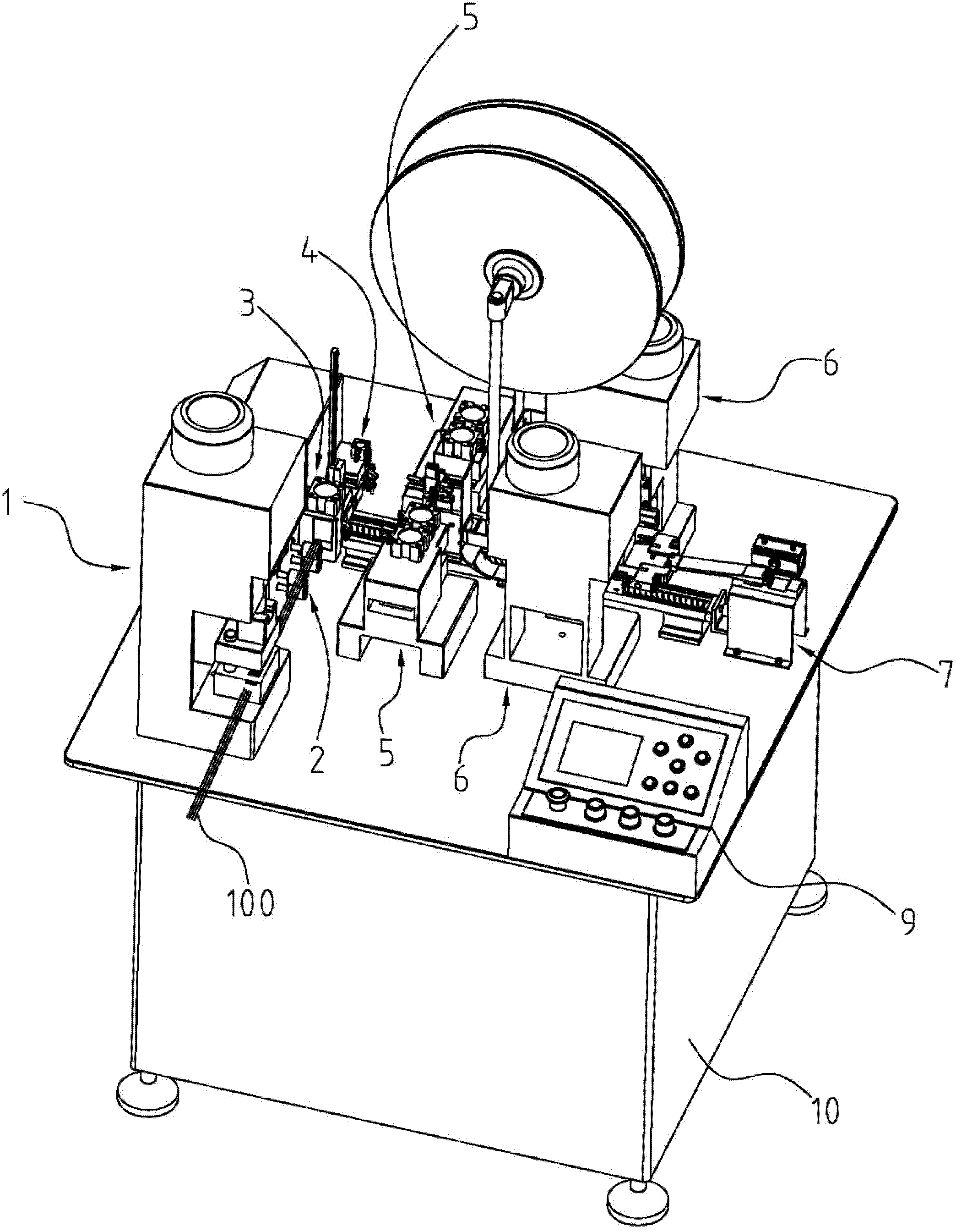
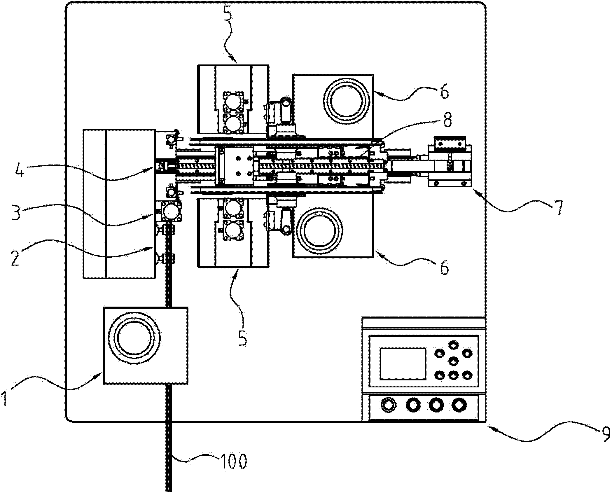
[0058] Such as figure 1 , 2 As shown, a fully automatic cable terminal crimping and integration device includes a workbench 10, a first stage of material transportation and a second stage of material transportation provided on the workbench 10. The first stage of the material conveying includes a wire splitter 1, a wire feeder 2 and a cutting machine 3 in order according to the material conveying direction; the second stage of the material conveying includes a material conveyor 8, a wire stripper 5, and a terminal crimping machine 6 And the unloading machine 7, the wire stripping machine 5 and the terminal crimping machine 6 are respectively symmetrically distributed on both sides of the movement track of the material conveyor 8. Between the first stage of material conveying and the second stage of material conveying, there is a shaping machine 4 whic...


PUM


Abstract

The invention discloses a full automatic busbar terminal crimping integration device and a crimping method. The device comprises a wire splitting machine, a wire feeding machine, a cutting machine, a shaping machine, a material conveying machine, a wire stripping machine and a terminal crimping machine, wherein the terminal crimping machine comprises a terminal driving mechanism and a wire feeding mechanism; the terminal driving mechanism mainly comprises a punching head and an automatic feeding mechanism; the wire feeding mechanism comprises a shaping groove, a compaction block, a compactionblock driving mechanism, a cam and a cam driving mechanism; one side of the cam clings to the shaping groove, and one side, which is far away from the shaping groove, of the cam is provided with a stop block; the distance between the stop block and the tail end of the shaping groove is equal to the diameter of single connecting wire in a busbar; and the cam aligns with the punching head of the terminal driving mechanism. The wire splitting machine, the cutting machine and the shaping machine are matched to finish the cutting and finishing of the busbar, the material conveying machine feeds cut busbar sections to the wire stripping machine and the terminal crimping machine for processing, and finally the terminal crimping at both ends of the busbar sections is finished; and the whole process is automatic, the production efficiency is high, and the device is convenient to operate.

Description

technical field [0001] The invention relates to connecting wire crimping equipment, in particular to a terminal crimping device and a crimping method suitable for a cable with multiple connecting wires. Background technique [0002] Connecting cables are widely used in signal transmission or power connection of computers, communication equipment, household appliances, and digital equipment. The connecting wires are divided into single or several thin wires bonded together with an adhesive, and the two ends of each connecting wire are crimped with terminals for connection with electronic equipment. At present, the terminal pressing of a single connecting wire adopts the computer-controlled connecting wire terminal pressing equipment to realize automatic pressing. The structure of the pressing equipment is composed of a computer control system, a terminal feeding mechanism, a terminal pressing mechanism and a connecting wire end stripping, feeding and cutting mechanism. Its ...

Claims


Application Information

Patent Timeline
IPC IPC(8): H01R43/048H01R43/05H01R43/052
Inventor 蒙功尧
Owner 蒙功尧
Why Eureka
Try Eureka