
Reflectance distribution curve modeling method, thickness measurement scheme and thickness measurement reflectometer using same

A modeling method and degree distribution technology, which is applied in semiconductor/solid-state device testing/measurement, instruments, measuring devices, etc., can solve problems such as inconsistencies, and achieve the effect of precise detection

Active Publication Date: 2013-10-16
SNU PRECISION CO LTD
View PDF4 Cites 0 Cited by
  • Summary
  • Abstract
  • Description
  • Claims
  • Application Information

AI Technical Summary

Problems solved by technology

[0005] However, when the light is incident in a specified wavelength band after passing through the band pass, there is a considerable error between the measured reflectance distribution curve and the reflectance distribution curve generated based on the existing modeling method, so Inconsistent
Therefore, the thickness of the film layer cannot be determined by existing modeling methods

Method used


Image

  • Reflectance distribution curve modeling method, thickness measurement scheme and thickness measurement reflectometer using same
  • Reflectance distribution curve modeling method, thickness measurement scheme and thickness measurement reflectometer using same
  • Reflectance distribution curve modeling method, thickness measurement scheme and thickness measurement reflectometer using same

Examples


Embodiment Construction

[0022] Embodiments of the method for modeling the reflectance distribution curve of the present invention, the method for thickness detection using the method, and the thickness detection reflector will be described in detail below with reference to the accompanying drawings.

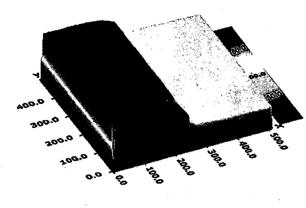
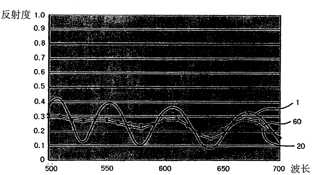
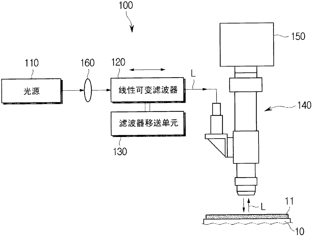
[0023] figure 1 is a schematic diagram of an embodiment of the thickness detection reflector of the present invention; figure 2 is through figure 1 Intensity distribution curve of the linear variable filter band-passed light in the thickness detection reflectometer; Figure 7 It is a drawing for explaining an example of the surface shape of the detected thin film layer.

[0024] Please refer to figure 1 , figure 2 and Figure 7 The thickness detection reflector 100 of this embodiment includes a light source 110 , a linear variable filter 120 , a filter transfer unit 130 , a condenser lens 160 , an optical system 140 and an imaging unit 150 .

[0025] The light source 110 is used for irradiating ...


PUM


Abstract

The reflectance distribution curve modeling method of the present invention is for modeling a reflectance distribution of a thin film layer according to a change in the wavelength of light with respect to a thin film layer having a uniform thickness, and comprises: a reflectance distribution curve preparation step whereby a reflectance distribution curve is prepared to represent reflectance distribution of the thin film layer according to a change in wavelength of light; an input intensity setting step whereby an intensity distribution curve is prepared to represent intensity of light in a certain wavelength band around a specific wavelength for which white light was band-passed, and then the intensity distribution curve is integrated within the wavelength band to set as an input intensity of the specific wavelength; an output intensity setting step whereby a combined intensity distribution curve of the reflectance and intensity distribution curves is integrated within the wavelength band to set an output intensity of the specific wavelength; an integrated reflectance setting step whereby a value obtained by dividing the output intensity of the specific wavelength by the input intensity of the specific wavelength is set as an integration reflectance of the thin film layer for the specific wavelength; and an integration reflectance distribution curve generating step whereby an integration reflectance distribution curve for reflecting the integration reflectance distribution according to a change in wavelength is generated by repeating the input intensity setting step, the output intensity setting step and the integration reflectance setting step, while changing the specific wavelength.

Description

technical field [0001] The invention relates to a method for modeling a reflectance distribution curve, a thickness detection method and a thickness detection reflector applying the method, and in particular to improving the reflection of a thin film layer on light passing through the band by means of integration in a predetermined wavelength band A reflectance distribution curve modeling method based on the degree distribution curve modeling method, a thickness detection method and a thickness detection reflectometer using the method. Background technique [0002] The thickness distribution of the transparent thin film layer, which is widely used in LCD and semiconductor fields, has a great influence on the subsequent process in terms of its characteristics. There is therefore a need throughout the industry for a system capable of monitoring film layer thickness. In thin film layer thickness detection, widely used devices include non-contact detection devices Interferomete...

Claims


Application Information

Patent Timeline
Patent Type & Authority Patents(China)
IPC IPC(8): G01B11/06H01L21/66
CPCG01B11/0625G01B11/0608G01B9/02012H04N23/56
Inventor 朴喜载安祐正金星龙
Owner SNU PRECISION CO LTD
Learn More