
Motor stator core automatic riveting device

A motor stator and power device technology, which is applied in the field of automatic riveting devices for motor stator cores, can solve problems such as rising labor costs, low work efficiency, and increasing the burden on small processing plants, so as to achieve safe and convenient operation, avoid safety accidents, and improve production efficiency effect

Inactive Publication Date: 2016-03-30
杭州高弘科技有限公司
View PDF6 Cites 0 Cited by
  • Summary
  • Abstract
  • Description
  • Claims
  • Application Information

AI Technical Summary

Problems solved by technology

The riveting process of the motor stator sheet involves a series of processes such as the arrangement and positioning of the stator sheet. The efficiency of manual operation is low and production accidents are prone to occur
In recent years, rising labor costs have further burdened small processing plants
In addition, the riveting of the stator sheet of the motor is either processed by a stamping device, or pressed and riveted by various riveting machines, but usually such equipment is not designed for this type of product, so the work efficiency is low, and it is not suitable for the stator sheet of the motor Large-scale batch riveting

Method used


Image

  • Motor stator core automatic riveting device
  • Motor stator core automatic riveting device
  • Motor stator core automatic riveting device

Examples


Embodiment 1

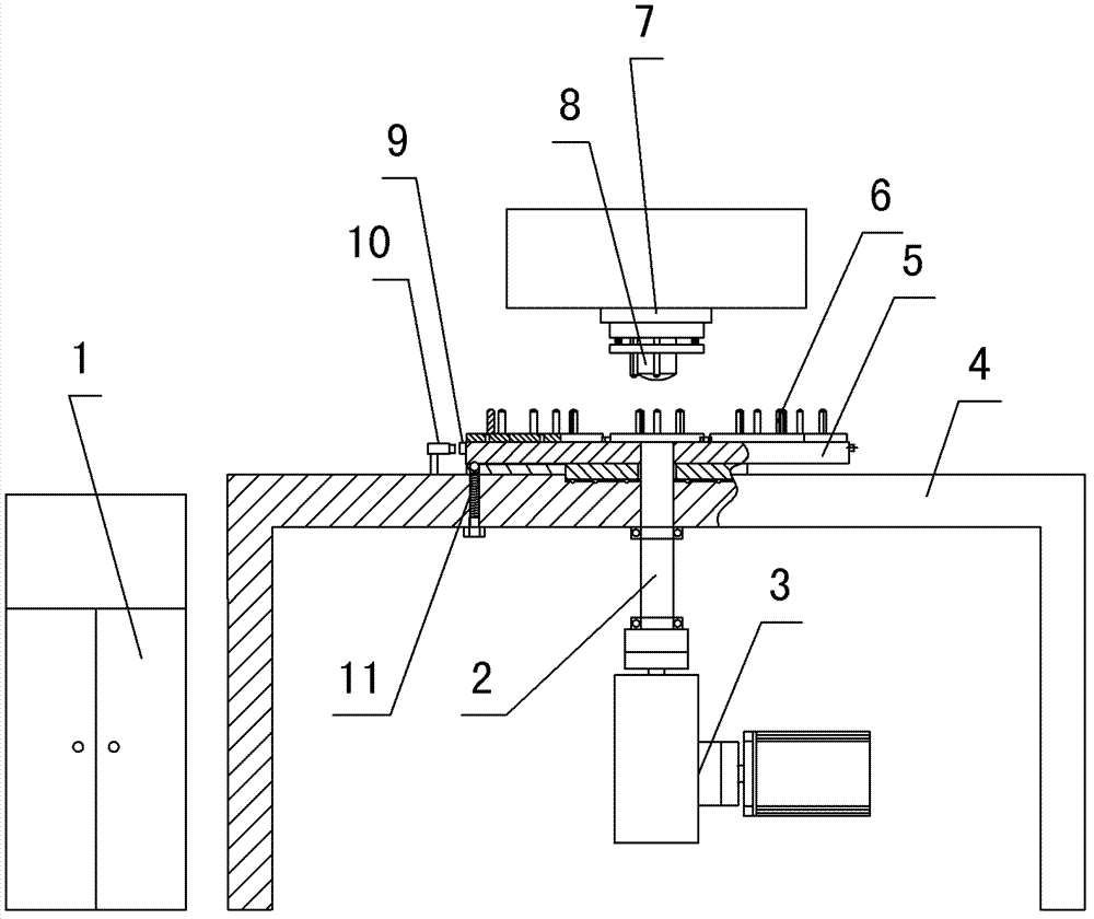
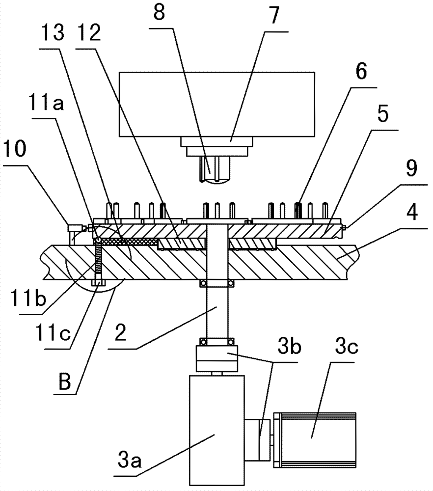
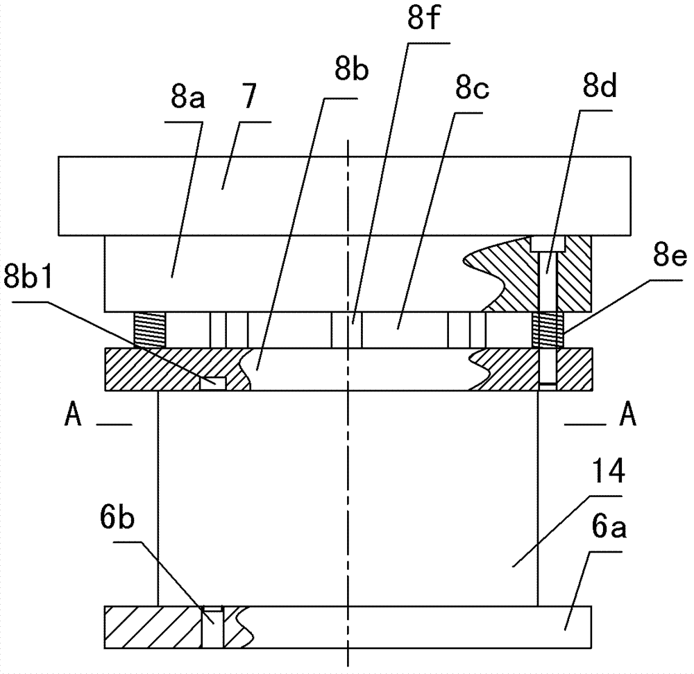
[0022] Embodiment 1: refer to Figure 1-8 . The motor stator core automatic riveting device includes a punching machine, the punching machine includes a machine table 4 and a mold handle 7, the upper end of the machine table 4 is provided with a turntable 5, one side of the turntable 5 is located between the machine table 4 and the mold handle 7, and the machine table 4 A power unit 3 is provided below, and the center of the turntable 5 is connected to the power unit 3 through a rotating shaft 2. The upper end of the turntable 5 is provided with a number of lower dies 6 evenly arranged around the rotating shaft 2. The lower end of the mold handle 7 is connected to each lower die. The mold 6 is matched with the upper mold 8 that is connected, and the power unit 3 includes a gearbox 3a and a motor 3c. The limit block 9 matched with the upper mold 8, the limit switch 10 that can be matched and connected with each limit block 9 is provided on the outside of the turntable 5, and t...

Embodiment 2

[0024] Embodiment 2: refer to Figure 1-8 . Place the motor stator iron core 14 on the lower mold on the turntable 5 in turn, the lower positioning pin 6c blocks the positioning hole 14a of the motor stator iron core 14, after pressing the start switch, the PLC controller controls the motor 3c to start running, after After the gearbox 3a connected by the coupling 3b is adjusted in speed, the power output by the motor is transmitted to the rotating shaft 2, and the turntable 5 is rotated through the rotating shaft 2 until the limit block 9 reaches the limit switch 10. At this time, The PLC controller controls the motor 3c to stop running, and at the same time, the positioning device positions the turntable, that is, the steel ball 11a pushes into the limit hole 5a to prevent it from continuing to rotate due to inertia and can accurately locate the position of the turntable 5, so that the stator core of the motor 14 is directly below the mold handle 7, and then the PLC controll...


PUM


Abstract

The invention relates to a device for automatically riveting a stator core of a motor. The device comprises a punching machine, wherein the punching machine comprises a machine bench and a die handle; a rotary disc is arranged on the machine bench; one side of the rotary disc is positioned between the machine bench and the die handle; a power device is arranged below the machine bench; a center of the rotary disc is in transmission connection with the power device by a rotating shaft; a plurality of lower dies which are arranged uniformly by taking the rotating shaft as a center are arranged at the periphery of the upper end of the rotary disc; the lower end of the die handle is connected with an upper die which is in matched connection with each lower die; the power device comprises a speed changing box and a motor; the power output end of the motor is connected with the speed changing box; the rotating shaft is in transmission connection with the speed changing box; a plurality of limit blocks which are matched with the upper die are arranged on the edge of the rotary disc; a limit switch which can be in matched connection with the limit blocks sequentially is arranged on the outer side of the rotary disc; a programmable logic controller (PLC) control box in which a PLC is arranged is arranged on one side of the machine bench; and the control end of the punching machine, the control end of the motor and the limit switch are connected with the PLC in the PLC control box by a communication cable.

Description

technical field [0001] The invention relates to a riveting machine, in particular to an automatic riveting device for a motor stator iron core. Background technique [0002] At present, due to the limited production scale and cost, most small factories use ordinary punches to process gold workpieces. The riveting process of the motor stator sheet involves a series of processes such as the arrangement and positioning of the stator sheet. The efficiency of manual operation is low and production accidents are prone to occur. In recent years, rising labor costs have further burdened small processing plants. In addition, the riveting of the stator sheet of the motor is either processed by a stamping device, or pressed and riveted by various riveting machines, but usually such equipment is not designed for this type of product, so the work efficiency is low, and it is not suitable for the stator sheet of the motor Mass riveting in batches. Contents of the invention [0003] T...

Claims


Application Information

Patent Timeline
Patent Type & Authority Patents(China)
IPC IPC(8): B21J15/10B21J15/26B21J15/38
Inventor 赵乃松赵晓峰
Owner 杭州高弘科技有限公司
Learn More