Water passage circulation structure for condensing heat exchanger

A technology of heat exchanger and circulation structure, applied in the field of water circuit circulation structure of condensing heat exchanger, can solve the problems of inconvenient maintenance, disassembly, cleaning and cleaning of residue and scale, short service life of heat exchanger, insufficient combustion of gas, etc., so as to reduce resources. Consumption, simple structure, sufficient heat exchange effect

Active Publication Date: 2012-02-29
WUXI XIZHOU MACHINERY
View PDF5 Cites 9 Cited by
  • Summary
  • Abstract
  • Description
  • Claims
  • Application Information

AI Technical Summary

Problems solved by technology

There are defects in the structural design of the existing heat exchanger. The gas cannot be fully burned in the combustion chamber, and the harmful gases of carbon monoxide and nitrogen oxides produced by insufficient combustion will cause serious pollution to the environment. At the same time, insufficient combustion of the gas will also waste gas energy
In addition, the design of the water circulation path of the existing heat exchanger is relatively complicated, which brings inconvenience to maintenance, dismantling, washing and cleaning of residues and scales, and the maintenance cost is relatively high, and the service life of the existing heat exchanger is not long. cost-effective

Method used


Image

  • Water passage circulation structure for condensing heat exchanger
  • Water passage circulation structure for condensing heat exchanger
  • Water passage circulation structure for condensing heat exchanger

Examples


Embodiment Construction

[0015] The present invention will be further described below in conjunction with specific drawings and embodiments.

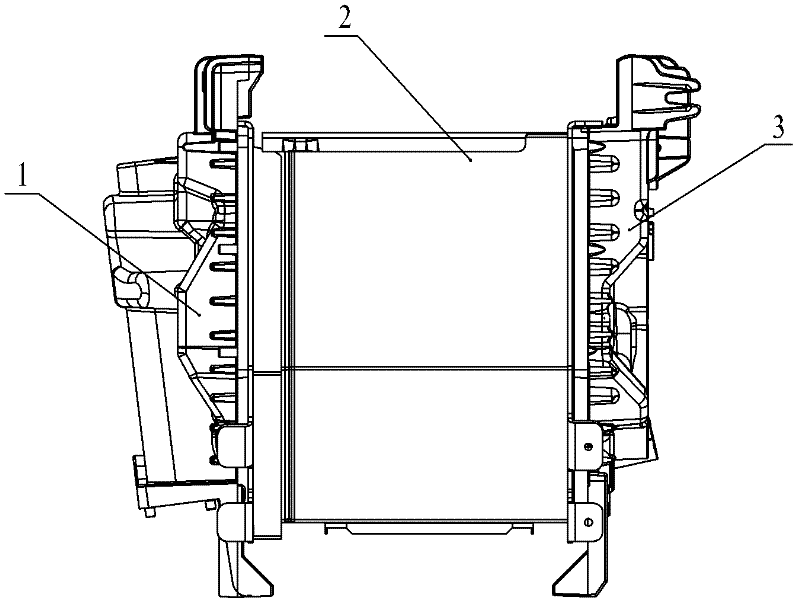
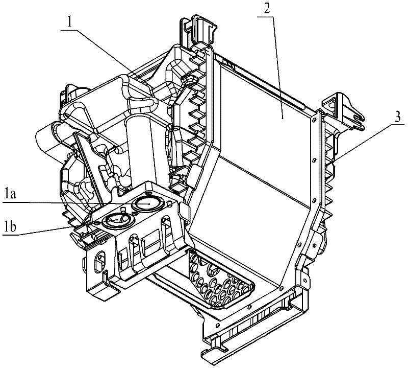
[0016] As shown in the figure: the water circulation structure of the condensing heat exchanger in the embodiment is mainly composed of a shell 2, a left cover plate 1, a right cover plate 3 and several straight-through pipes for heat dissipation.

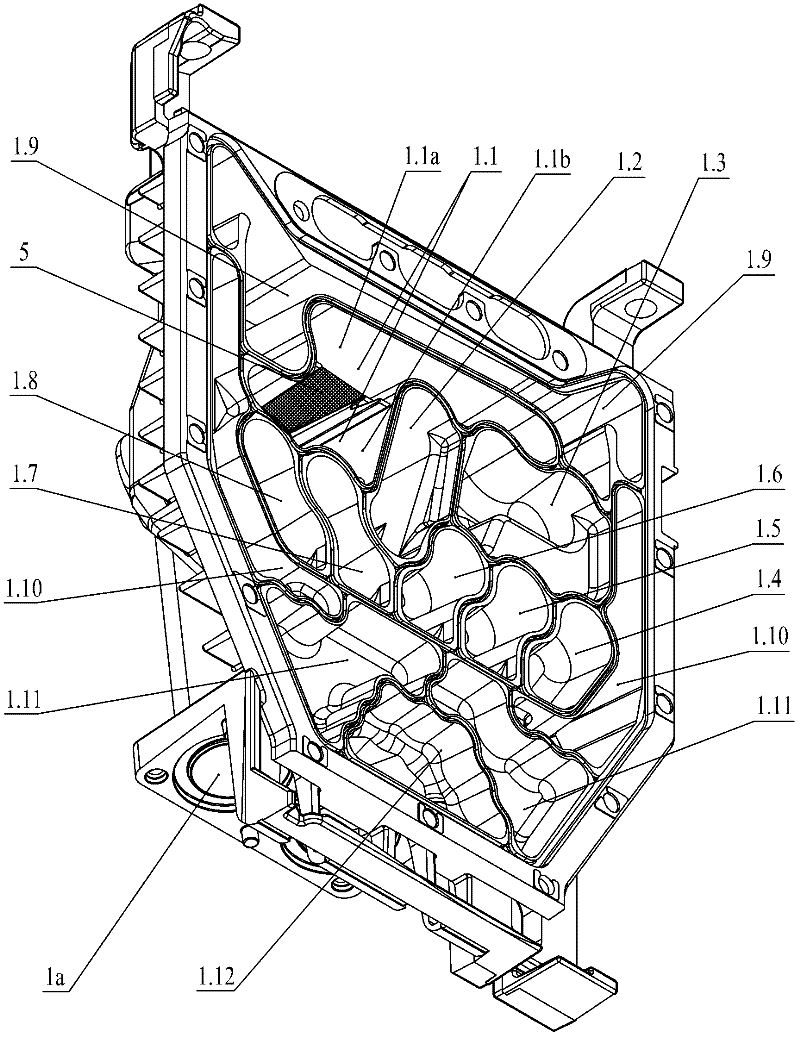
[0017] Such as Figure 1~Figure 3 As shown, the left cover plate 1 and the right cover plate 3 are installed on the left and right side walls of the housing 2, and the left cover plate 1 and the right cover plate 3 have chambers; the left cover plate 1 is provided with a water inlet 1a and Water outlet 1b, the chamber of the left cover plate 1 is divided into fourteen independent left water circulation areas by curved partitions, and the fourteen left water circulation areas are the first left water circulation area according to the order of water flow 1.1, the second left water circulation area 1.2, the third left...


PUM


Abstract

The invention relates to a water passage circulation structure for a condensing heat exchanger. The water passage circulation structure comprises a shell, and a left cover plate and a right cover plate which are provided with cavities, wherein the left and right cover plates are arranged on the left and right side walls of the shell. The water passage circulation structure is characterized in that: the left cover plate is provided with a water inlet and a water outlet; the cavity of the left cover plate is divided into a plurality of independent left water circulating areas; one is communicated with the water inlet, and another independent left water circulating area is communicated with the water outlet; the cavity of the right cover plate is divided into a plurality of independent rightwater circulating areas; the plurality of left water circulating areas on the left cover plate and the plurality of right water circulating areas on the right cover plate are connected and matched through asymmetrical layer-staggered radiating straight pipes in the mode; and water spirally circulates in a W-shaped route among the left cover plate, the radiating straight pipes and the right cover plate and flows out of the water outlet on the left cover plate finally. The water passage circulation structure is novel; and the heat exchanger with the water passage circulation structure has a medium volume, longer service life, and higher thermal efficiency, and is energy-saving and durable.

Description

technical field [0001] The invention relates to a heat exchanger, in particular to a water circuit circulation structure of a condensing heat exchanger. Background technique [0002] At present, there are various forms and types of heat exchangers produced at home and abroad, and heat exchangers are widely used in heating equipment systems in homes, shopping malls, hotels and other places. Traditional heat exchangers are usually large in size, low in heat transfer rate, and high in heat loss. For the heat exchanger, whether the gas can be fully combusted in the combustion chamber formed by the heat dissipation through-pipeline directly affects the conversion efficiency of the heat exchanger. There are defects in the structural design of the existing heat exchanger. The gas cannot be fully burned in the combustion chamber, and the harmful gases of carbon monoxide and nitrogen oxides produced by insufficient combustion will cause serious pollution to the environment. At the s...

Claims


Application Information

Patent Timeline
Patent Type & Authority Applications(China)
IPC IPC(8): F24H9/00
Inventor 包建忠
Owner WUXI XIZHOU MACHINERY
Why Eureka
Try Eureka