Control device and method for interleaved parallel LLC (Logical Link Control) resonant converter

A resonant converter and resonant conversion technology, applied in the direction of output power conversion device, control/regulation system, DC power input conversion to DC power output, etc., can solve the problems of high cost of control scheme and complicated control

Inactive Publication Date: 2012-02-29
SHANGHAI UNIV
View PDF3 Cites 25 Cited by
  • Summary
  • Abstract
  • Description
  • Claims
  • Application Information

AI Technical Summary

Problems solved by technology

[0006] The purpose of the present invention is to provide a control device and method for LLC resonant converters with interleaved parallel operation for the defects of high cost and complex control of existing control schemes

Method used


Image

  • Control device and method for interleaved parallel LLC (Logical Link Control) resonant converter
  • Control device and method for interleaved parallel LLC (Logical Link Control) resonant converter
  • Control device and method for interleaved parallel LLC (Logical Link Control) resonant converter

Examples


Embodiment 1

[0052] Preferred embodiments of the present invention are described in detail as follows in conjunction with accompanying drawings:

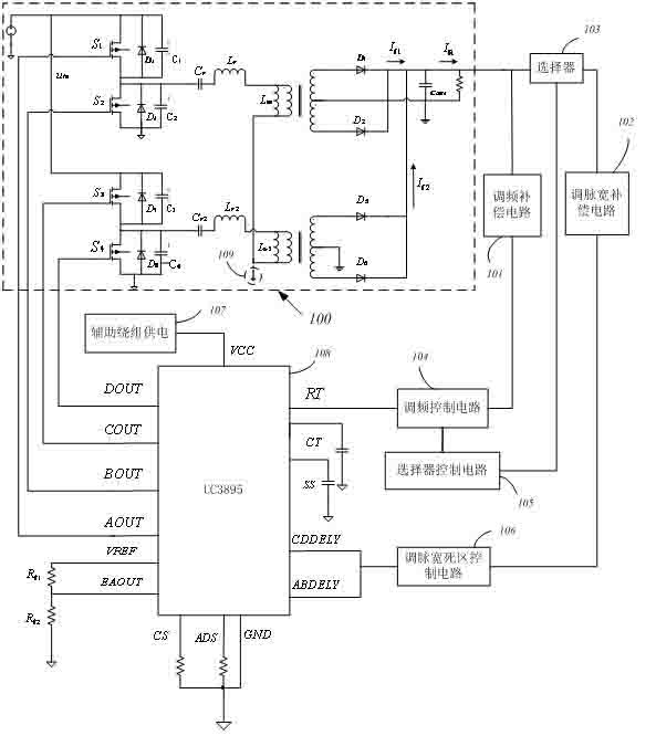
[0053] see figure 1 A control device for interleaved parallel LLC resonant converters, including a main circuit (100) composed of two LLC resonant converters, characterized in that the interleaved parallel LLC resonant converters are controlled by a control circuit based on a full-bridge phase-shifting chip UCC3895 Main circuit (100); when the circuit works at light load, adjust the output pulse width of the chip UCC3895 (108) through the dead zone feedback compensation link; when the circuit works at heavy load, adjust the chip UCC3895 (108) through the frequency modulation feedback compensation link output frequency, and by modifying the coupling transformer of the main circuit (100) of the interleaved parallel LLC resonant converter , The connection mode of the primary side improves the current sharing of the secondary side circuit. The ...

Embodiment 2

[0068] The control method of the interleaved parallel LLC resonant converter is used to control the above-mentioned device, and is characterized in that the control step is as follows: when the circuit operates under heavy load, the interleaved parallel resonant converter circuit is controlled by a frequency modulation closed loop, including a frequency modulation compensation circuit (101), Frequency modulation control circuit (104) and selector control circuit (105):

[0069] (1) The FM compensation circuit (101) includes an optocoupler (408), regulator tube (419) and the resistors and capacitors that make up the compensation of two zeros and three poles, where the voltage regulator tube (419) Use TL431 to facilitate zero-pole adjustment. One of the zeros is placed at the high-frequency pole of the LLC, one zero is placed at the double pole of the LLC circuit, one pole is placed at the ESR zero, one is placed at half the resonant frequency, and the other pole is the pol...


PUM


Abstract

The invention relates to a control device and method for an interleaved parallel LLC (Logical Link Control) resonant converter. The device comprises a set of interleaved parallel LLC resonant converter main circuit (100) and is characterized in that the interleaved parallel LLC resonant converter main circuit (100) is controlled by a control circuit based on a full bridge phase-shift chip UCC3895; when the circuit works at a light load, the output pulse width of a chip UCC3895 (108) is adjusted through a dead zone feedback compensation link; when the circuit works at a heavy load, the output frequency of the chip UCC3895 (108) is adjusted through a frequency-adjusting feedback compensation link; and equalizing current of a secondary circuit is improved by modifying a connecting mode of a coupling transformer of the interleaved parallel LLC resonant converter main circuit (100) and a primary end. According to the invention, the interleaved parallel LLC resonant circuit is not limited by application occasions of a traditional LLC main control chip and is suitable for high-power occasions; the circuit is simplified; and the robustness is improved.

Description

technical field [0001] The invention belongs to the field of communication power supply and LED lighting, and in particular relates to a control device and method of a parallel LLC resonant converter. Background technique [0002] LLC resonant converter has the characteristics of high efficiency, wide frequency range modulation and high reliability, and gradually replaces the full-bridge phase-shift topology as the main circuit of communication, server and lighting power supply. The MOS tube on the primary side of the LLC resonant converter can realize zero-voltage turn-on in a wide frequency range, and can improve its own efficiency with the increase of the input voltage of the primary side, which is more suitable for working in the back end of the power factor correction circuit. Since the half-bridge LLC resonant converter is only suitable for transmission of power below 3KW, the LLC resonant converter running in parallel can meet the transmission of power above 3KW. [...

Claims


Application Information

Patent Timeline
Patent Type & Authority Applications(China)
IPC IPC(8): H02M3/335
CPCY02B70/10
Inventor 廖文高艳霞余定轩钮悦
Owner SHANGHAI UNIV
Why Eureka
Try Eureka