Ship engine control system

A technology for control systems and ships, applied in engine control, machines/engines, motor-driven engines, etc., can solve problems such as engine failure and failure to obtain response performance, and achieve the effect of improving fuel efficiency

Inactive Publication Date: 2012-02-29
MITSUI ENG & SHIPBUILD CO LTD
View PDF5 Cites 6 Cited by
  • Summary
  • Abstract
  • Description
  • Claims
  • Application Information

AI Technical Summary

Problems solved by technology

However, in bad weather, since the load torque generated by the propeller changes rapidly, sufficient responsiveness cannot be obtained in the PID control using the speed-up that assumes sailing under normal weather conditions, and engine failure due to overspeed may occur. danger

Method used


Image

  • Ship engine control system
  • Ship engine control system
  • Ship engine control system

Examples


Embodiment Construction

[0035] Hereinafter, embodiments of the present invention will be described with reference to the drawings.

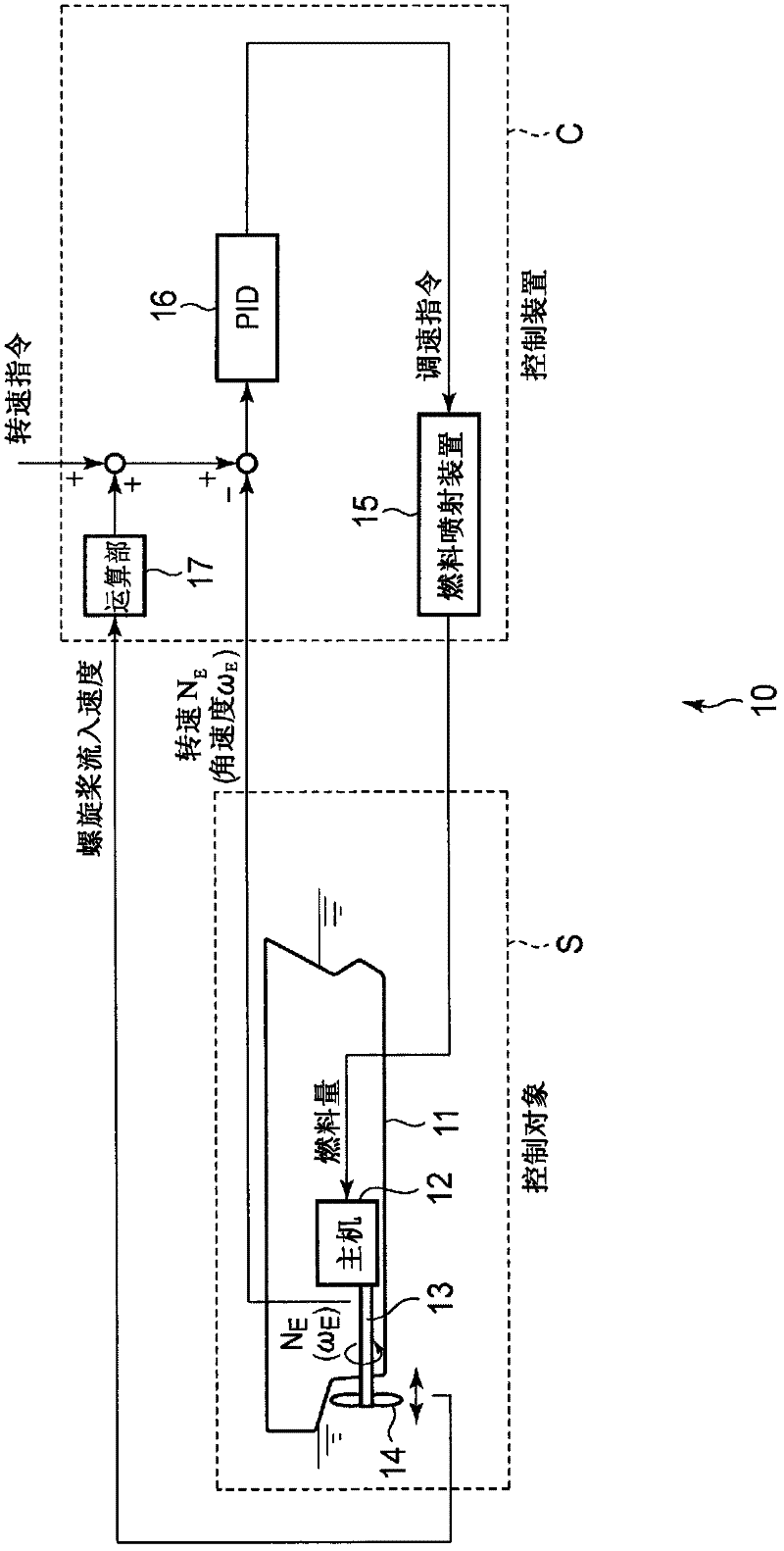
[0036] figure 1 It is a block diagram which shows the whole structure of the marine engine control system concerning 1st Embodiment of this invention.

[0037] The marine engine control system 10 of the present embodiment uses the hull 11 , the main engine 12 , the main shaft 13 , the propeller 14 , etc. as control objects S, and supplies fuel from the fuel injection device (actuator) 15 of the control device C in the main engine 12 . The main shaft 13 connecting the main engine 12 and the propeller 14 is provided with detection of the actual rotation speed N of the main shaft 13 or the main engine 12 E (or angular velocity ω E ) of a known rotational speed (angular velocity) sensor (not shown).

[0038] The control system 10 performs, for example, PID control using the spindle rotation speed (or engine rotation speed) as a rotation speed command (target value), and ...


PUM


Abstract

A main engine is operated at an efficient rotational frequency to match fluctuations in propeller inflow velocity, and fuel efficiency is increased. The divergence between a rotational frequency command and measured variations in rotational frequency (NE) of a main axle (13) or the main engine (12) is inputted into a proportional-integral-derivative (PID) computation unit (16), and feedback control is performed on the quantity of fuel supplied from a fuel injection device (15) to the main engine (12). The propeller inflow velocity of a propeller (14) is detected and inputted into a computation unit (17). The rotational frequency command is adjusted such that the control point moves along an efficiency curve in response to fluctuations in propeller inflow velocity.

Description

technical field [0001] The present invention relates to a control system of a marine engine, in particular, to the rotational speed control of the marine engine. Background technique [0002] In the control of the marine engine, PID (proportional-integral-derivative) control is performed so that there is no difference between the set target rotational speed and the actual rotational speed. However, in bad weather, the load torque generated by the propeller changes rapidly, so in the PID control that utilizes the acceleration of sailing under normal weather conditions, sufficient response performance cannot be obtained, and there is an engine failure due to overspeed. danger. In response to such a problem, a configuration in which the acceleration of the PID control is changed by predicting the fluctuation of the propeller rotation speed due to disturbance has been proposed (Patent Document 1). [0003] Patent Document 1: Japanese Patent Application Laid-Open No. 8-200131 ...

Claims


Application Information

Patent Timeline
Patent Type & Authority Applications(China)
IPC IPC(8): F02D29/02B63H5/07B63H21/12
CPCB63H21/14F02D29/02B63H5/07B63H21/12
Inventor 稻见昭一宫田淳也
Owner MITSUI ENG & SHIPBUILD CO LTD
Why Eureka
Try Eureka