Equipment and method for impregnating continuous long fiber reinforced thermoplastics

A technology for enhancing thermoplastics and impregnating equipment, which is applied in the impregnation of continuous long fiber reinforced thermoplastics and impregnation equipment for continuous long fiber reinforced thermoplastics. Rotation and other issues, to increase interaction, improve impregnation effect, and ensure easy cleaning

Active Publication Date: 2012-03-07
SICHUAN UNIV
View PDF5 Cites 19 Cited by
  • Summary
  • Abstract
  • Description
  • Claims
  • Application Information

AI Technical Summary

Problems solved by technology

The addition of the godet roll will inevitably increase the space of the impregnated flow channel, which will make it difficult to control the temperature and flow rate of the melt, and may cause the temperature and flow rate of the melt in each part to be different, which is not suitable for the production of heat-sensitive resins.
And the godet roller needs to correspond to the continuous long fiber bundles of various specifications, which makes the generality of this method not strong and increases the equipment cost
Since the godet roller must rotate in the production process to effectively reduce the force on the fiber monofilament, when producing high-viscosity resin, the godet roller is difficult to rotate in high-viscosity resin and is easily damaged, so it is not suitable for high-viscosity resin production
[0004] Although the above two methods can disperse the fiber bundles, the monofilament fibers are all impregnated in the same impregnation flow channel, and the fiber bundles will inevitably interfere with the nearby melt during the movement, so that the melt pressure at the nearby fiber bundles changes, which makes the fiber bundles interact with each other, resulting in unstable product quality

Method used


Image

  • Equipment and method for impregnating continuous long fiber reinforced thermoplastics
  • Equipment and method for impregnating continuous long fiber reinforced thermoplastics
  • Equipment and method for impregnating continuous long fiber reinforced thermoplastics

Examples


Embodiment Construction

[0026] The present invention will be further described below in conjunction with the accompanying drawings.

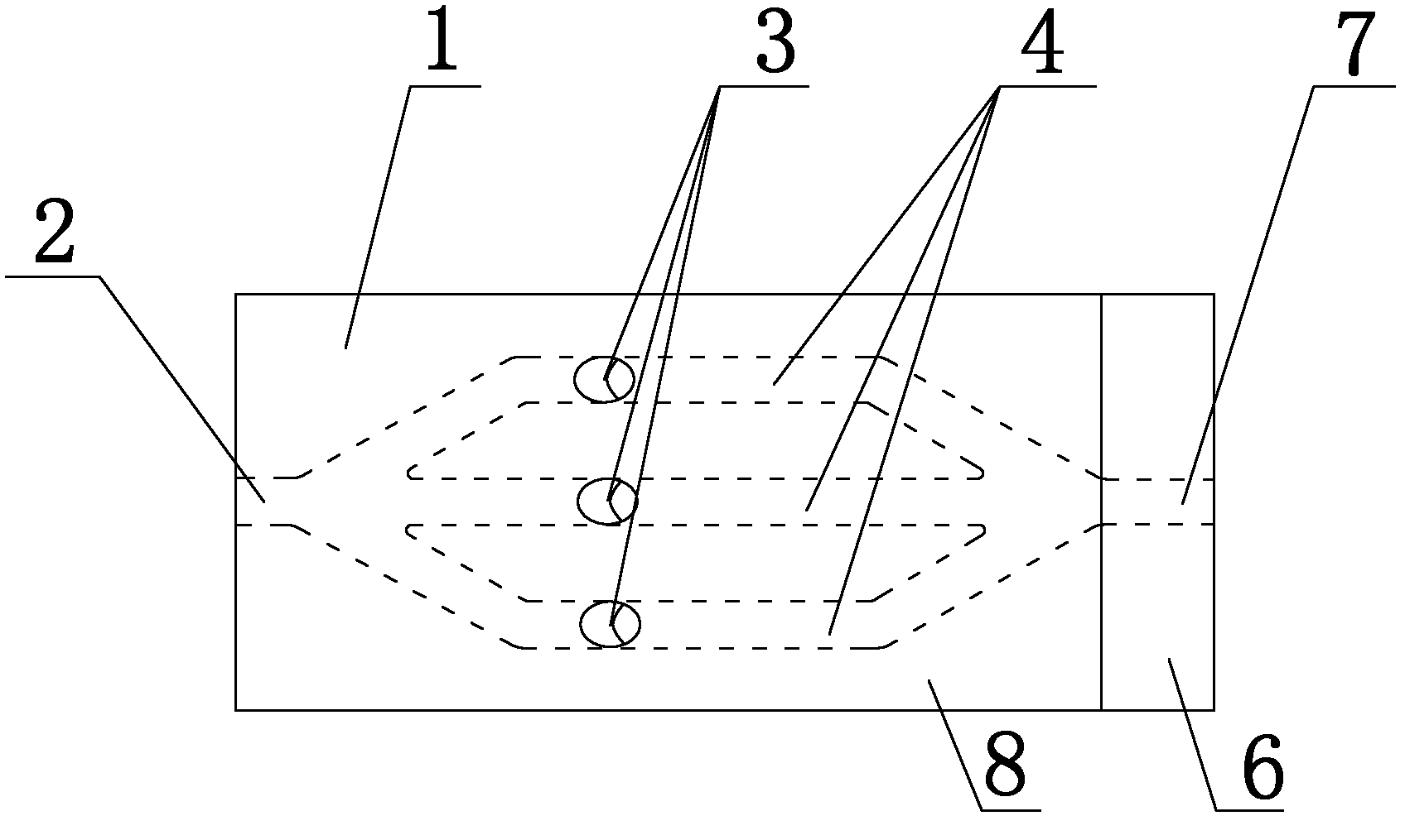
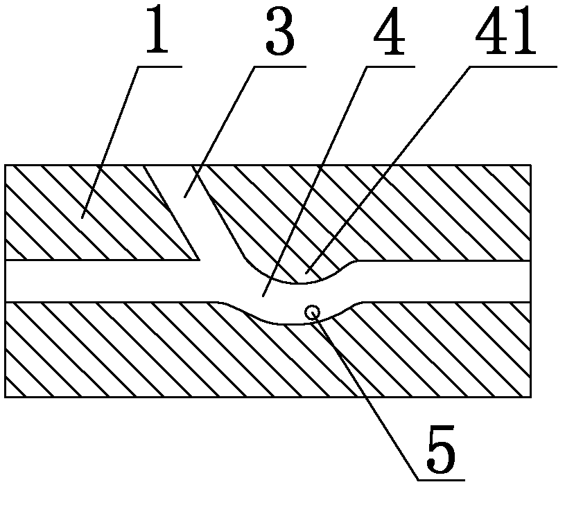
[0027] like figure 1As shown, the present invention includes an equipment outer body 1 , the upstream end of the equipment outer body 1 is provided with a melt inlet 2 , the downstream end of the equipment outer body 1 is provided with an extrusion port 7 , and the inside of the equipment outer body 1 An immersion channel 4 is provided, and the two ends of the immersion channel 4 are respectively communicated with the melt inlet 2 and the extrusion port 7. At least two of the immersion channels 4 are arranged in parallel. The side wall of 1 is provided with the same number of long fiber inlets 3 as the impregnation channels 4 , and the long fiber inlets 3 are respectively communicated with each impregnation channel 4 . The upstream end of the outer body 1 of the equipment is the end of the feed, which is based on the flow direction of the melt; similarly, the downstre...


PUM


Abstract

The invention discloses equipment and a method for impregnating, and particularly relates to equipment and a method for impregnating continuous long fiber reinforced thermoplastics. The invention provides the equipment and the method for impregnating the continuous long fiber reinforced thermoplastics of which the fiber bundles are not interfered with one another, which comprise an equipment outer body, wherein a melt inlet is arranged at the upstream end of the equipment outer body, an extruding outlet is arranged at the downstream end of the equipment outer body, impregnating runners are arranged in the equipment outer body, the two ends of the impregnating runners are respectively communicated with the melt inlet and the extruding outlet, at least two impregnating runners are arranged in parallel, and long fiber feed ports which have the same number as that of the impregnating runners are arranged on the side wall of the equipment outer body and are respectively communicated with each impregnating runner. Because each impregnating runner is separately arranged, fibers can be separately impregnated and fed, and are not interfered with one another, so the production can be ensured to be stable.

Description

technical field [0001] The invention relates to an impregnation device, in particular to an impregnation device for continuous long fiber reinforced thermoplastics. In addition, the present invention also relates to an impregnation method, especially an impregnation method of continuous long fiber reinforced thermoplastics. Background technique [0002] Continuous long fiber reinforced thermoplastic resin is a reinforced thermoplastic resin in which reinforcing fibers are unidirectionally arranged and whose length is equal to the length of resin pellets. Compared with conventional staple fibers, it has more excellent mechanical properties, dynamic fatigue resistance, and warpage resistance. The study of continuous long fiber reinforced thermoplastics has important research significance and industrial value to promote the development of composite materials and expand the application of fiber reinforced composite materials in industry. Long fiber reinforcement technology is ...

Claims


Application Information

Patent Timeline
Patent Type & Authority Applications(China)
IPC IPC(8): B29C70/50B29C70/52B29C70/54
Inventor 杨杰吴玉倩王孝军张刚龙盛如
Owner SICHUAN UNIV
Why Eureka
Try Eureka