Material conveying pipe

A technology for conveying pipes and materials, which is applied in the field of conveying pipelines for solid materials, and can solve problems such as poor versatility, large installation space, and complex structures.

Active Publication Date: 2012-03-07
BEIJING GUODIAN FUTONG SCI & TECH DEV
View PDF9 Cites 6 Cited by
  • Summary
  • Abstract
  • Description
  • Claims
  • Application Information

AI Technical Summary

Problems solved by technology

However, the problem is that for some materials with a high flow rate, deposition and blockage often occur instantaneously. When the material is deposited and accumulated rapidly, the flow channel of the compressed air is rapidly reduced or even completely blocked. At this time , the compressed air has no way to go, cannot flow to the deflector, and cannot change the flow direction through the deflector, and cannot play the role of anti-blocking
However, the flow-aiding device still has the following problems: first, the molding process is relatively complicated, because holes need to be opened on the pipeline, and each hole must correspond to a flow-aiding branch pipe, although the process of opening the holes is not difficult, but, Each hole must be sealed with the flow-aid branch pipe, which increases the difficulty of the process; at the same time, each flow-aid branch pipe is connected with the flow-aid pipe, and the flow-aid branch pipe and the flow-aid pipe also need to be sealed. Further increase the difficulty of the process
Second, the flow aid device adop

Method used


Image

  • Material conveying pipe
  • Material conveying pipe
  • Material conveying pipe

Examples


Embodiment Construction

[0053] The core purpose of the present invention is to provide an anti-clogging material conveying pipe, which is mainly used for conveying solid materials, especially solid powder materials.

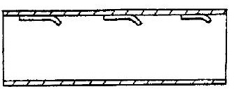
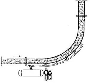
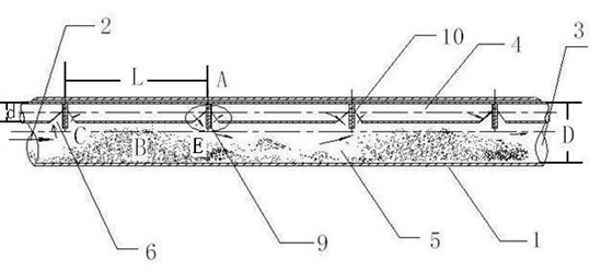
[0054] Specific embodiments of the present invention will be described in detail below in conjunction with the accompanying drawings. image 3 It is a structural schematic diagram of an embodiment of the material conveying pipeline of the present invention; Figure 4 yes image 3 Enlarged view of part A in the middle; Figure 5 It is a schematic structural diagram of the material conveying pipeline of the present invention with a connector; Image 6 It is the material deposition data of the material conveying pipe provided by the present invention and the material conveying pipe in the prior art during the process of conveying lime; Figure 7 It is the condition of the compressed air source used for conveying power in the material conveying pipe of the present invention in the proce...


PUM

PropertyMeasurementUnit
Diameteraaaaaaaaaa
Diameteraaaaaaaaaa

Abstract

The invention relates to a solid material conveying pipeline, and in particular relates to a conveying pipeline capable of preventing materials from blocking. The material conveying pipe provided by the invention comprises an external pipe; one end of the external pipe is a feeding port; the other end of the external pipe is a discharging port; the upper pipe wall in the external pipe is fixedly fitted with an internal pipe; a material channel is formed between the external wall of the internal pipe and the internal wall of the external pipe; a plurality of flowing-aided through holes distributed along the length direction of the internal pipe are formed on the pipe wall of the internal pipe towards the material channel; and a flowing-aided plate passing through the flowing-aided through holes and stretching in the material channel is extended downwards from the upper pipe wall in the internal pipe. As the flowing-aided through holes and the flowing-aided plate are adopted, the material conveying pipe provided by the invention can effectively prevent blocking.

Description

technical field [0001] The invention relates to a conveying pipeline for solid materials, in particular to a conveying pipeline capable of preventing material clogging. Background technique [0002] A major problem in the transportation of solid materials is that some solid materials are easy to bond with moisture in the air, thus depositing on the pipeline during the transportation process, causing pipeline blockage. For example, the sintered ash powder of a steel plant is generally a white powder material, which is mainly obtained by the following chemical reaction when limestone (CaCO3) is calcined: [0003] [0004] Therefore, the main component of the white powdery material is CaO, its chemical properties are very unstable, and the following chemical reactions will occur when exposed to the air: [0005] [0006] During the transportation process, the compressed air for transportation is fully mixed with the white powdery material, which is more likely to promote...

Claims


Application Information

Patent Timeline
IPC IPC(8): B65G53/34B65G53/52
Inventor 丁岩峰张春霞孙奉昌杜岩刘新华李新生
Owner BEIJING GUODIAN FUTONG SCI & TECH DEV
Why Eureka
Try Eureka