Quickly-separated disconnecting switch

An isolating switch and fast technology, which is applied in the field of quick disconnect isolating switches, can solve the problems of reducing the reliability and service life of high-voltage switchgear, unable to realize fast opening function, slow separation speed of static arc contacts, etc. Ability to convert current and small capacitive current, reduce arcing time and arc reburning times, simple and reliable structure

Active Publication Date: 2014-03-12
XIAMEN HUADIAN SWITCHGEAR
View PDF5 Cites 0 Cited by
  • Summary
  • Abstract
  • Description
  • Claims
  • Application Information

AI Technical Summary

Problems solved by technology

During the opening process, the separation speed of the moving contact and the moving arc contact is the same, and they are all controlled by the operating mechanism, so the separation speed of the moving and static arc contacts is relatively slow, and it is impossible to realize the fast opening function, cut off the bus conversion current and cut off When the capacitive current is small, the arc reignites more times, which reduces the reliability and service life of the high-voltage switchgear
[0003] If the existing high-voltage switchgear needs to have a quick opening function, an electric spring operating mechanism is usually used to drive the contact movement. It also has the following disadvantages: 1. It requires high operating power of the mechanism and relatively high cost; 2. The high-voltage switchgear commonly used at present does not use an electric spring operating mechanism due to the limitation of space structure and economical considerations, and the contacts do not have the ability to quickly separate

Method used


Image

  • Quickly-separated disconnecting switch
  • Quickly-separated disconnecting switch
  • Quickly-separated disconnecting switch

Examples


Embodiment Construction

[0045] first preferred embodiment

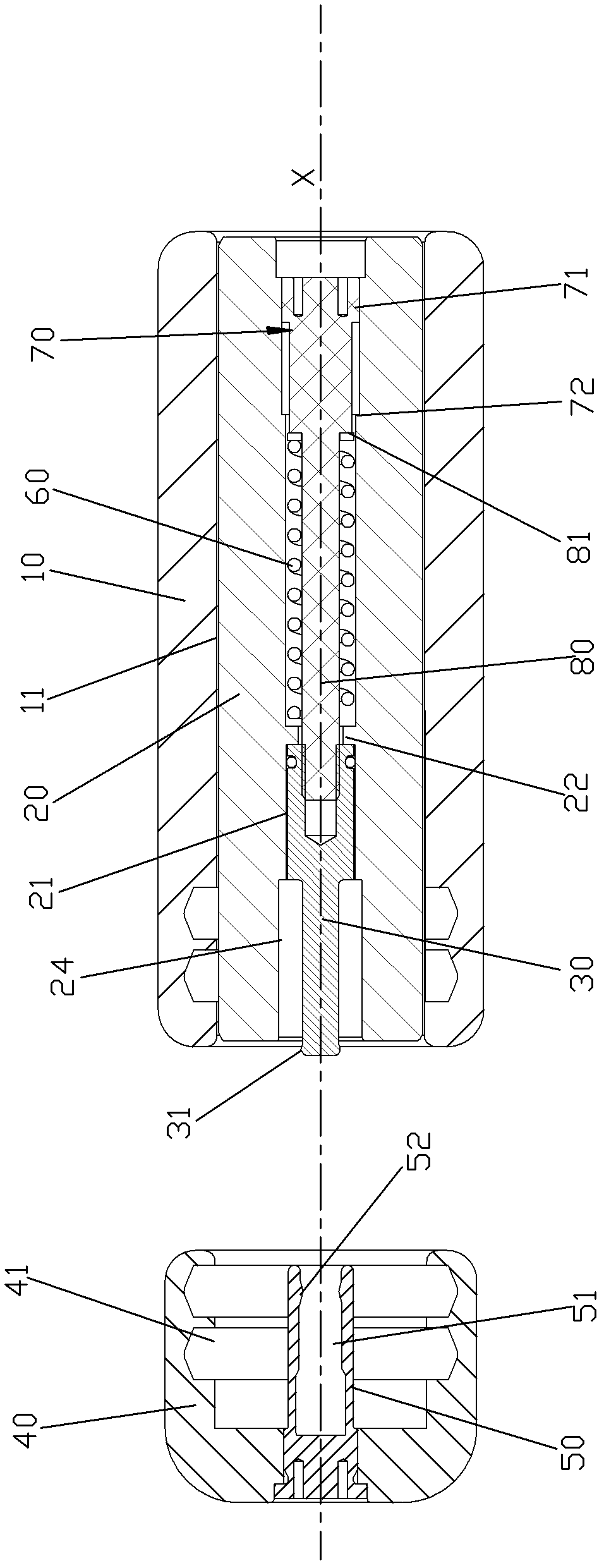
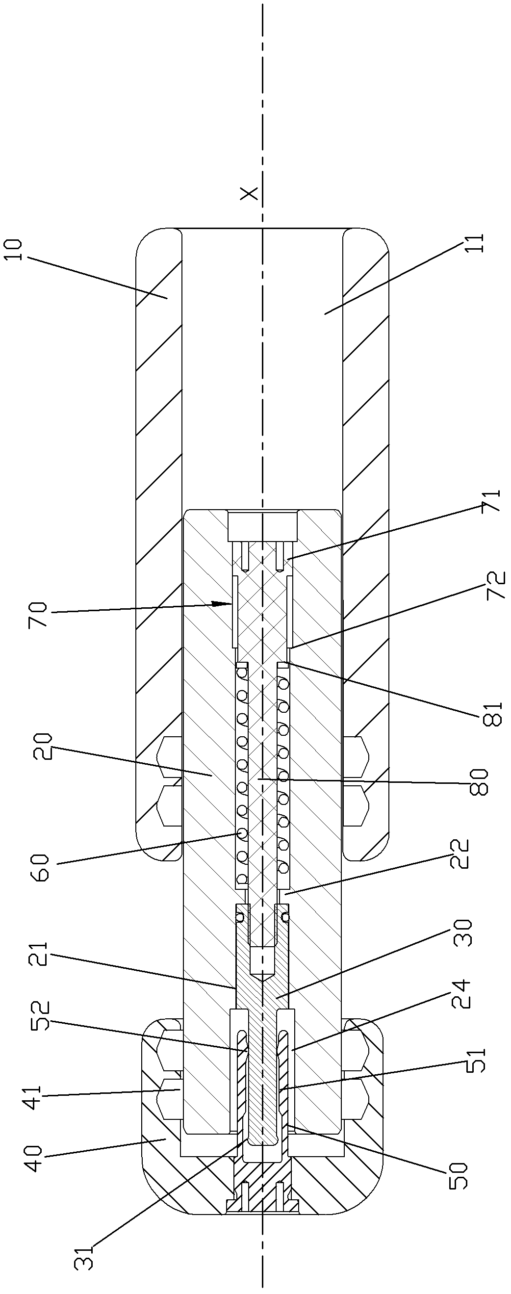
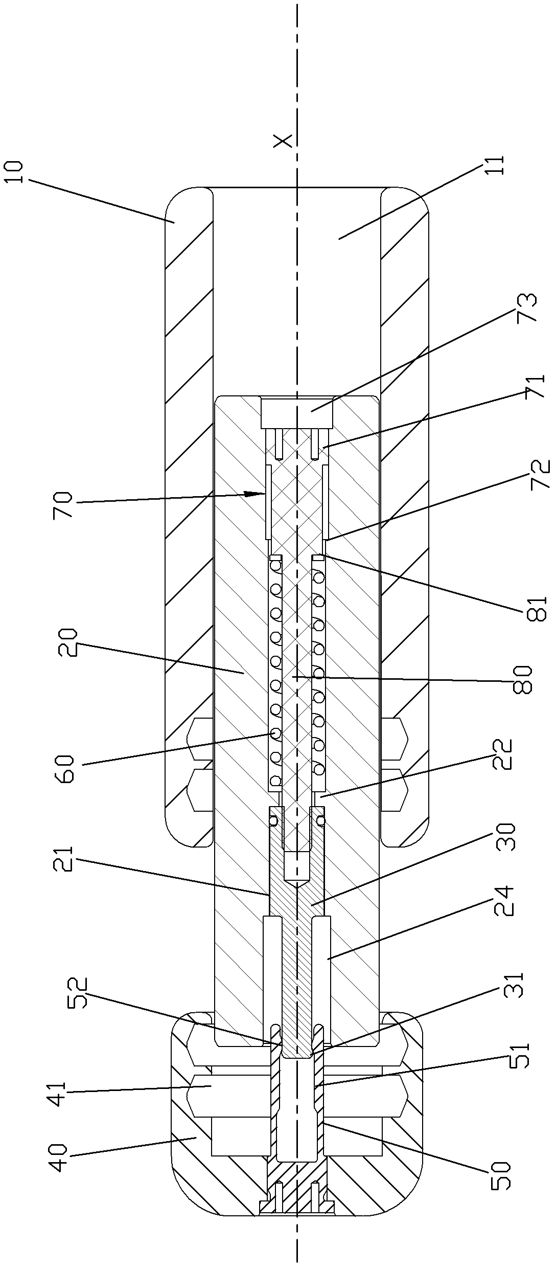
[0046] Please check Figure 1 to Figure 4, quick separation isolating switch, which includes an outer seat 10, a moving contact 20, a moving arc contact 30, a static contact 40, a static arc contact 50, an elastic body 60, a limit mechanism 70 and a continuous Rod 80.

[0047] The outer seat 10 is provided with a first sliding hole 11 along the line X. In this embodiment, the first sliding hole 11 is cylindrical, and the line X is the axis of the first sliding hole 11 .

[0048] The moving contact 20 is slidably arranged in the first sliding hole 11 so that the moving contact 20 can slide along the first sliding hole 11 under the action of the operating mechanism. In this embodiment, the movable contact 20 is a rotating body. The movable contact 20 is in conductive contact with the outer seat 10 . In this embodiment, in order to ensure the electrical conductivity, a contact guiding spring is provided between the outer revolving wall of th...


PUM


Abstract

The invention discloses a quickly-separated disconnecting switch, comprising an outer seat, a moving contact, a moving arcing contact, a fixed contact, a fixed arcing contact, an elastic body and a limiting mechanism, wherein the moving arcing contact can slide relative to the moving contact; the elastic body can store energies when the moving contact slides away from the moving arcing contact; the limiting mechanism is used for arranging the relative sliding extreme positions between the moving contact and the moving arcing contact; an outer ring at the tail end of the outer wall of the moving arcing contact is provided with a male buckle in a raised mode; an inner ring at a port of the inner wall of a second conductive slot of the fixed arcing contact is provided with a female buckle; the moving contact is far away from the fixed contact in the process of separating brake; the male buckle is coordinated with the female buckle to connect the moving arcing contact with the fixed arcing contact, the moving contact slides away from the moving arcing contact oppositely, and the elastic body stores the energies; and after the moving contact slides away from the moving arcing contact oppositely to the extreme position, the moving arcing contact is separated from the fixed arcing contact under the action of the limiting mechanism, and the energies stored by the elastic body are released to quickly separate the moving arcing contact from the fixed arcing contact.

Description

technical field [0001] The invention relates to a quick disconnect disconnector. Background technique [0002] Early isolating switch, which includes outer seat, moving contact, moving arc contact, static contact and static arc contact, the moving contact and moving arc contact are fixed, and the static contact and static arc contact The head is fixed. Under the action of the operating mechanism, the movable contact can slide relative to the outer seat so as to be movable between the closing state and the opening state. During the opening process, the separation speed of the moving contact and the moving arc contact is the same, and they are all controlled by the operating mechanism, so the separation speed of the moving and static arc contacts is relatively slow, and it is impossible to realize the fast opening function, cut off the bus conversion current and cut off When the capacitive current is small, the number of arc restrikes is high, which reduces the reliability a...

Claims


Application Information

Patent Timeline
Patent Type & Authority Patents(China)
IPC IPC(8): H01H1/44H01H3/30
Inventor 郑闽生吴忠白刚
Owner XIAMEN HUADIAN SWITCHGEAR
Why Eureka
Try Eureka