Element centering device of component inserter

A technology of alignment device and plug-in machine, which is applied in the direction of assembling printed circuits, electrical components, and electrical components with electrical components. High degree, fast running speed, stable running effect

Active Publication Date: 2014-06-25
海宁经开产业园区开发建设有限公司
View PDF4 Cites 0 Cited by
  • Summary
  • Abstract
  • Description
  • Claims
  • Application Information

AI Technical Summary

Problems solved by technology

[0003] In the prior art, the components are generally manually inserted into the printed circuit board one by one, and the printed circuit board is rarely inserted using an automated plug-in machine. Therefore, it is possible to match the automatic plug-in machine to align the components. There are also very few centering devices, and the existing small number of centering devices still have the disadvantages of slow running speed, low degree of automation control, low machine running accuracy and unstable operation

Method used


Image

  • Element centering device of component inserter
  • Element centering device of component inserter
  • Element centering device of component inserter

Examples


Embodiment 1

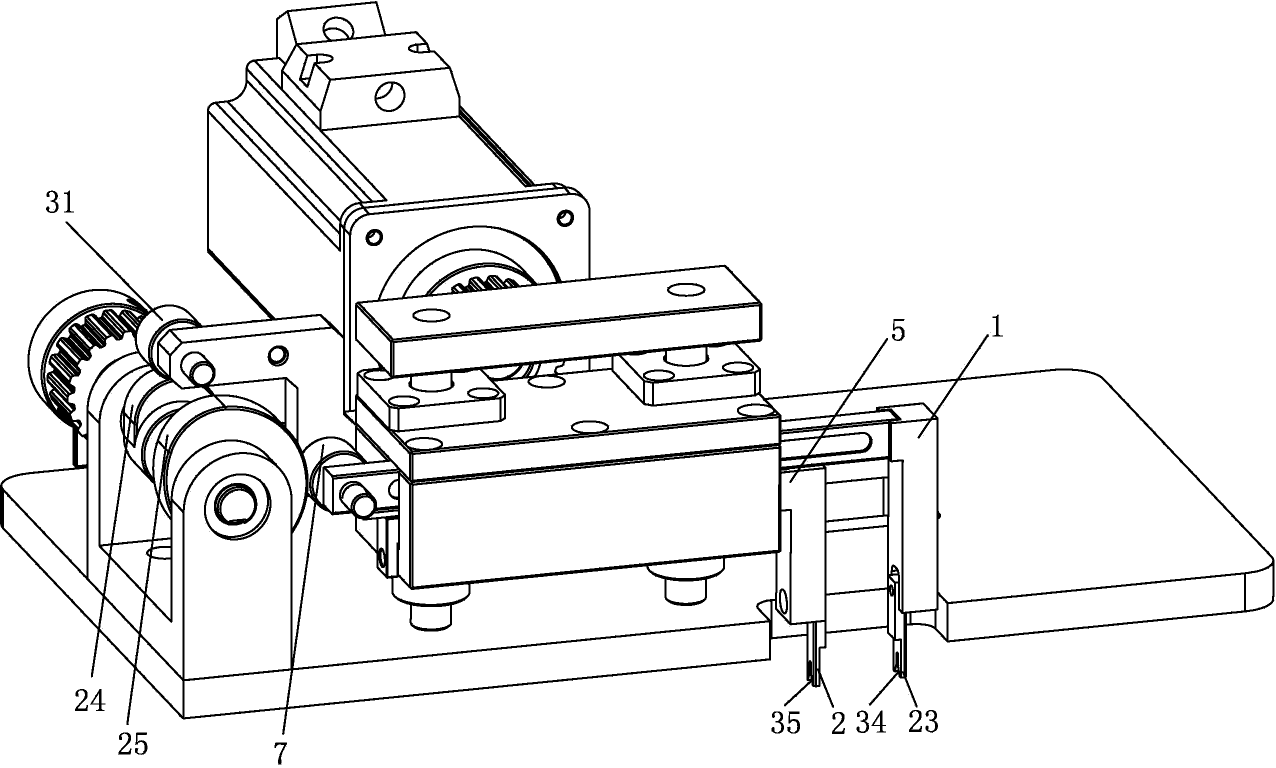
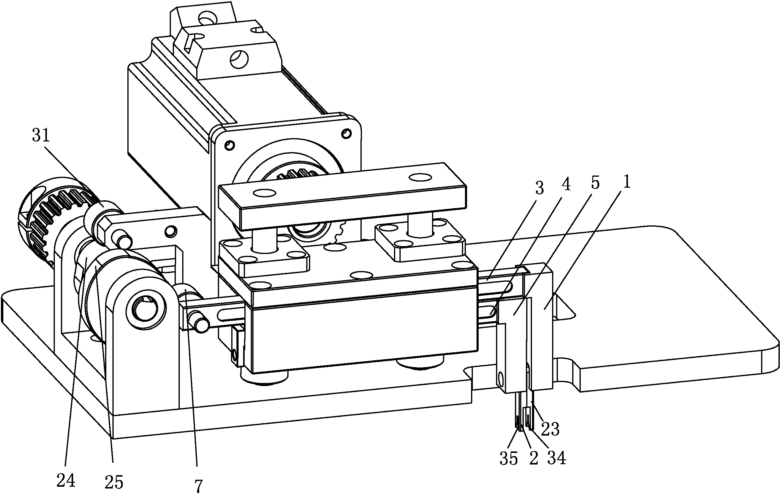
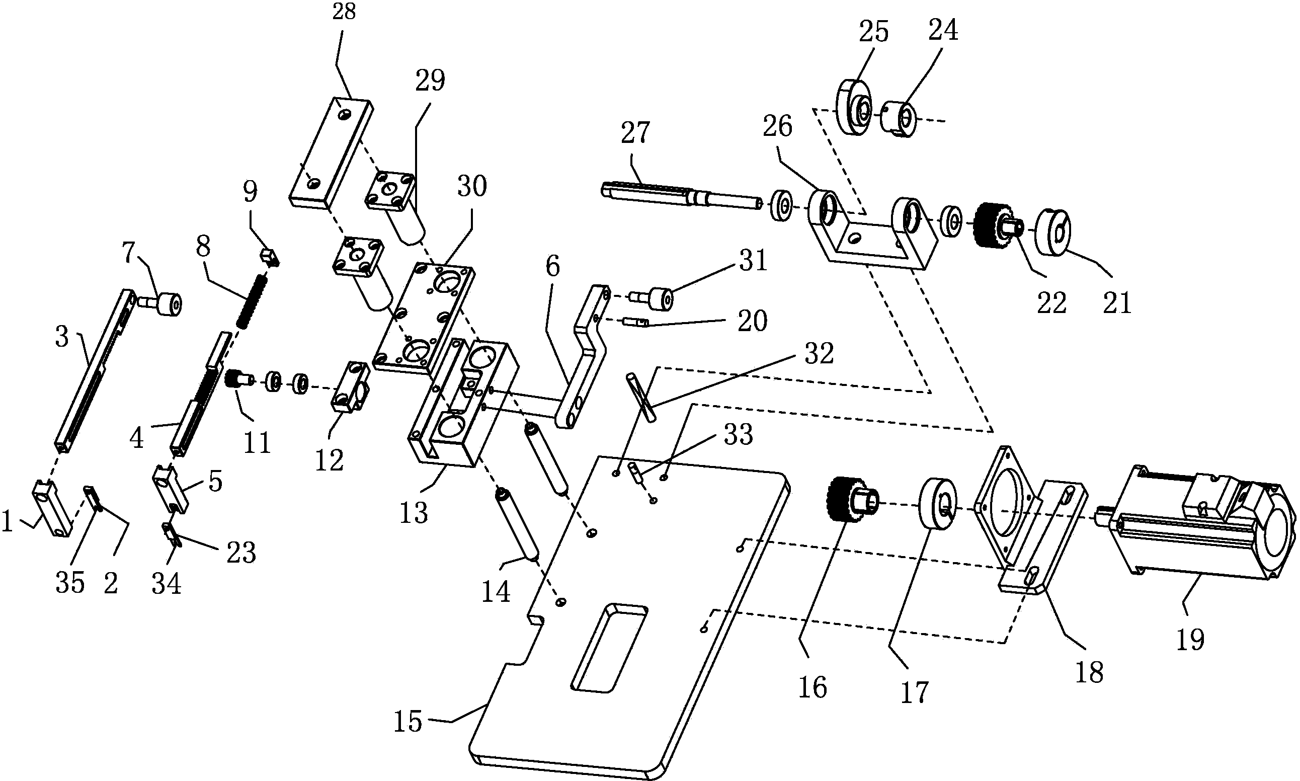
[0032] A component centering device of a plug-in machine in this embodiment such as Figure 1 to Figure 4 As shown, it includes a base 13, a centering opening and closing device and a driving device. The centering opening and closing device is arranged on the base 13; the centering opening and closing device is provided with a gear 11 and an upper rack 3 and a lower rack 4 parallel to each other. , the upper rack 3 and the lower rack 4 are meshed with the gear 11, the driving device is provided with a left and right cam 25 and a device for driving the left and right cam 25 to rotate, and the left and right cam 25 is arranged on one side of the upper rack 3 and resists the upper gear One end of the bar 3, the upper rack 3 and the lower rack 4 are respectively provided with clamping parts perpendicular to the upper rack 3 and the lower rack 4.

[0033] A reset device is also provided, one end of the reset device is set on the base 13 , and the other end of the reset device is se...

Embodiment 2

[0036] A component centering device for a plug-in machine, the other structures of this embodiment are the same as those of Embodiment 1, the difference is that: the upper rack is provided with a right clamping part, the lower rack is provided with a left clamping part, and the right clamping part The parts include an upper rack connecting block 1 and a right centering piece 23, the upper rack 3 connecting block 1 is vertically connected with the upper rack 3, one end of the right centering piece 23 is arranged on the upper rack connecting block 1 and the right centering piece The other end of 23 is exposed below the upper rack connection block 1, and the other end of the right centering piece 23 is provided with a first positioning groove 34;

[0037] The left clamping part includes a lower rack connecting block 5 and a left centering piece 2, the lower rack connecting block 5 is vertically connected with the lower rack 4, one end of the left centering piece 2 is arranged on t...

Embodiment 3

[0045] A component centering device of a plug-in machine, the other structure of this embodiment is the same as that of Embodiment 1, the difference is that: the base 13 is also provided with a spring stopper 9, and one end of the first return spring 8 is connected to the spring stopper 9 , the other end of the first return spring 8 is connected to the lower rack 4 .

[0046] When the first return spring 8 is compressed, the provided spring stopper 9 can provide a blocking force for the first return spring 8 .

[0047] The driving device is also provided with upper and lower cams 24 coaxial with the left and right cams 25 . The up and down cam 24 is used to control the up and down movement of the centering tensioning device.

[0048] A centering base plate 15 is also provided, and the base 13 is arranged on the centering base plate 15. The centering base plate 15 is also provided with a camshaft seat 26. The upper and lower cams 24 and the left and right cams 25 are arranged ...


PUM


Abstract

The invention relates to the component inserter technology field, especially relating to an element centering device of a component inserter. The device comprises a pedestal, a centering opening closing device and a drive device. The centering opening closing device is provided with a gear, and an upper tooth bar and a lower tooth bar which are in parallel. The drive device is provided with a left and right cam and a power apparatus driving rotation of the left and right cam. The left and right cam is provided at one side of the upper tooth bar and presses against one end of the side of the upper tooth bar. The upper tooth bar and the lower tooth bar are respectively provided with clamping elements which are perpendicular to the upper tooth bar and the lower tooth bar. In the invention, the drive device drives motion of the left and right cam, the left and right cam drives the upper tooth bar, when the upper tooth bar moves rightwards, the gear drives the lower tooth bar to move leftwards, when the upper tooth bar moves leftwards, the gear drives the lower tooth bar to move rightwards, with linkage of the upper tooth bar, the lower and the gear, clamping material is carried out, a centering function of a component is realized, an operation speed is fast, an automation control degree is high, machine operation precision is high, and operation is stable.

Description

technical field [0001] The invention relates to the technical field of plug-in machines, in particular to a component centering device of the plug-in machine. Background technique [0002] The plug-in machine is generally a mechanical device that automatically and standardly inserts some regular or even irregular plug-in electronic components into the conductive through holes of the printed circuit board. The advantages of the automatic plug-in machine include: increasing the installation density, improving the anti-vibration ability, improving labor efficiency and reducing production costs, etc. It generally includes circuit system, air system, 3X-Y positioning system, plug-in head assembly, bending and shearing anvil, automatic calibration system, automatic retractable board system, sequencer and component stack, component detector, etc., in order to To make the component rules available, the components need to be centered during the transmission process. Therefore, a cen...

Claims


Application Information

Patent Timeline
Patent Type & Authority Patents(China)
IPC IPC(8): H05K13/04H05K3/30
Inventor 皮俊君黎任坚钟承武曾翔清陈卓标
Owner 海宁经开产业园区开发建设有限公司
Why Eureka
Try Eureka