Shell and tube heat exchanger

A shell-and-tube heat exchanger and heat exchange tube technology, applied in the direction of heat exchanger shell, indirect heat exchanger, heat exchanger type, etc., can solve the problem of low heat transfer performance of heat transfer surface and achieve uniform liquid separation , Improve the heat transfer coefficient and improve the effect of heat transfer

Inactive Publication Date: 2012-03-14
SHANGHAI HANYE REFRIGERATION MACHINERY +1
View PDF6 Cites 11 Cited by
  • Summary
  • Abstract
  • Description
  • Claims
  • Application Information

AI Technical Summary

Problems solved by technology

[0005] The technical problem to be solved by the present invention is to provide a shell and tube heat exchanger in order to overcome the defect of low heat transfer performance of the heat transfer surface in the prior art

Method used


Image

  • Shell and tube heat exchanger
  • Shell and tube heat exchanger
  • Shell and tube heat exchanger

Examples


Embodiment Construction

[0022] The preferred embodiments of the present invention are given below in conjunction with the accompanying drawings to describe the technical solution of the present invention in detail.

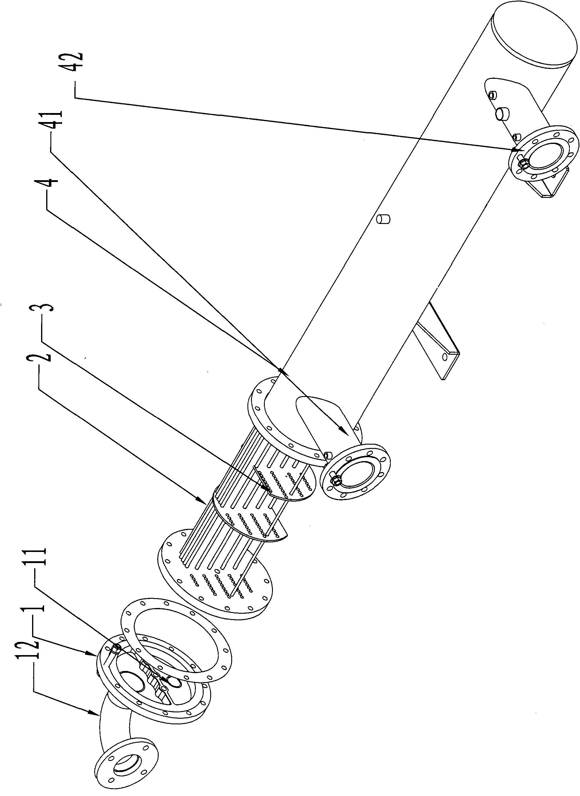
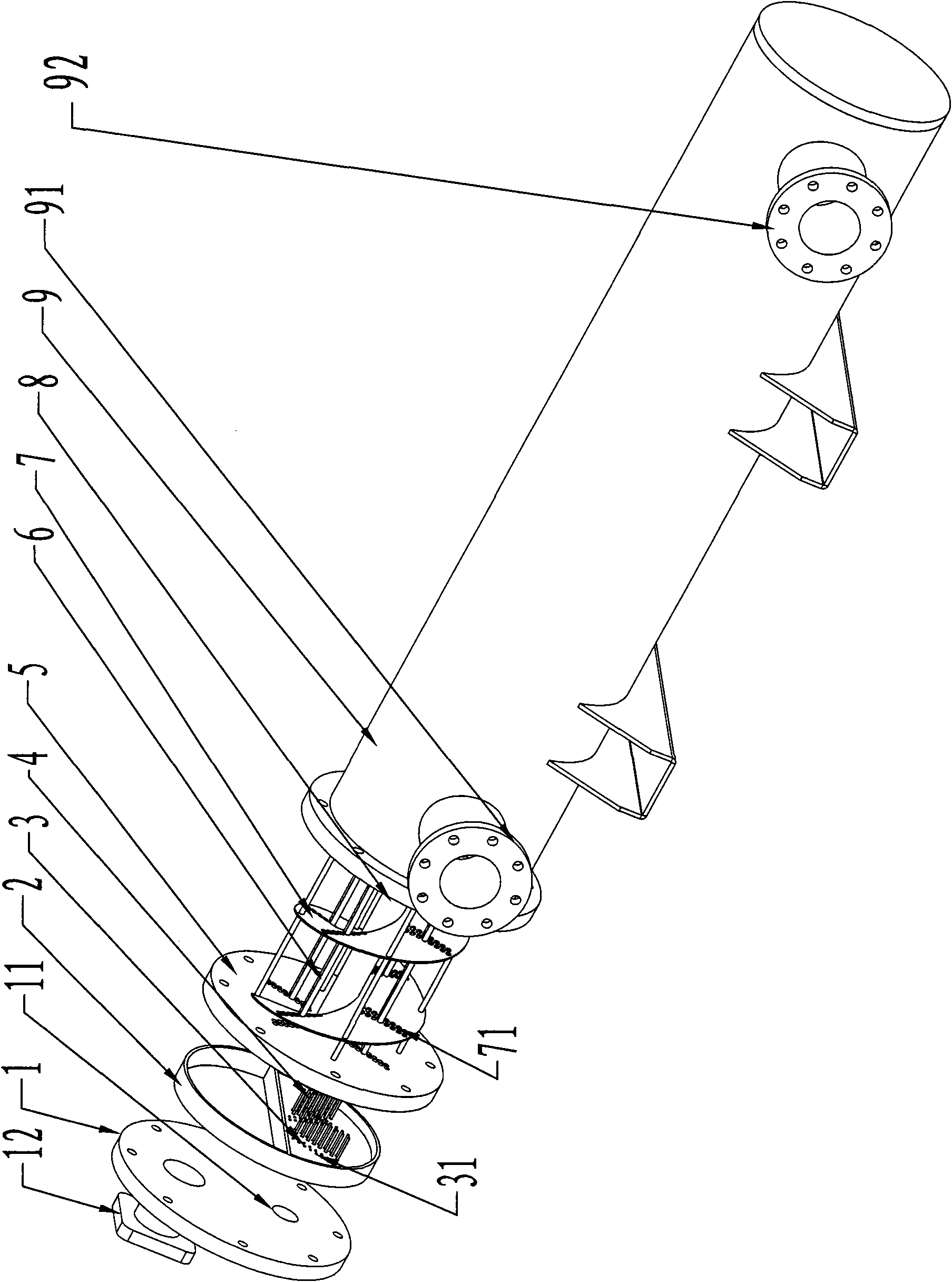
[0023] In this embodiment, the present invention is used as a "dry cold-only evaporator" in refrigeration as an example, as figure 2 As shown, the whole shell-and-tube heat exchanger system is divided into two kinds of working medium strokes: refrigerant stroke and brine stroke.

[0024] In the refrigerant stroke: the low-temperature and low-pressure refrigerant liquid enters the lower half of the tube box 2 from the refrigerant inlet 11 arranged at the lower part of the end plate 1, and a liquid separator 3 is arranged in the lower half of the tube box 2. The liquid plate 3, the bottom half of the tube box 2 and the end plate 1 form a narrower space 21, and in this space 21, the liquid is evenly distributed to some liquid pipes 4 arranged on the liquid separator plate (such as Figure...


PUM


Abstract

The invention discloses a shell and tube heat exchanger, which comprises an end plate, a channel and a core group, wherein the core group comprises a tube plate and a plurality of U-shaped internal-thread heat exchange tubes; the lower half part of the channel is provided with a liquid division plate; the liquid division plate, the channel and the end plate form a sealed space; the liquid division plate is provided with a plurality of liquid division tubes; and the first ends of the liquid division tubes and the U-shaped internal-thread heat exchange tubes are in tight coupling. In the shell and tube heat exchanger, the liquid division tubes and the liquid division plates are combined to evenly divide a refrigerating fluid, and the heat exchange area of each heat exchange tube is fully utilized. The spiral traverse baffle structure is used so as to increase the turbulence performance, a heat transfer coefficient is improved, and a heat exchange effect is greatly improved.

Description

technical field [0001] The invention relates to a heat exchanger used in an air-conditioning system, in particular to a shell-and-tube heat exchanger. Background technique [0002] The shell and tube heat exchanger is composed of shell, heat exchange tube bundle, tube sheet, baffle (baffle) and tube box and other components. The shell is mostly cylindrical, with a tube bundle inside, and the two ends of the tube bundle are fixed on the tube sheet. Two fluids, hot and cold, for heat exchange, one flows inside the tube and the other flows outside the tube. Usually, installing several baffles in the shell can improve the heat transfer coefficient of the fluid outside the tube, and the baffles can also increase the velocity of the fluid in the tube, forcing the fluid to pass through the tube bundle multiple times according to the specified distance, and enhance the degree of fluid turbulence. [0003] figure 1 It is the traditional shell and tube heat exchanger used in the cu...

Claims


Application Information

Patent Timeline
Patent Type & Authority Applications(China)
IPC IPC(8): F28D7/00F28F9/02F28F9/24F28F21/08F25B39/02
Inventor 吴松王信
Owner SHANGHAI HANYE REFRIGERATION MACHINERY
Why Eureka
Try Eureka