Calibration method of camera

A camera calibration and camera technology, which is applied in the field of computer vision, can solve problems such as long calculation time and interference, and achieve the effects of stable calibration results, improved stability, and strong search capabilities

Active Publication Date: 2012-03-14
TSINGHUA UNIV
View PDF2 Cites 5 Cited by
  • Summary
  • Abstract
  • Description
  • Claims
  • Application Information

AI Technical Summary

Problems solved by technology

[0003] In the prior art, the commonly used camera calibration method mostly utilizes certain inherent properties and relations in the imaging geometry to obtain some parameters first, and then uses these obtained parameters to solve other parameters, commonly known as the two-step method, the prior art The problem is that the result of the first step parameter in this method is particularly important to the calculation of the subsequent parameter results, so it is required to use enough points to ensure that the first step can obtain a more accurate solution
[0004] Since the process of camera calibration can be considered as an optimization process, an optimization method is introduced to optimize and solve it. The second step in the two-step method uses traditional optimization methods, such as gradient descent method and Newton iteration method. The problem with the introduction of optimization methods is that these optimization methods all have a common disadvantage that the calculation takes a long time and is easily disturbed by the calculation results of the first step.

Method used


Image

  • Calibration method of camera
  • Calibration method of camera
  • Calibration method of camera

Examples


Embodiment Construction

[0027] Embodiments of the present invention are described in detail below, examples of which are shown in the drawings, wherein the same or similar reference numerals designate the same or similar elements or elements having the same or similar functions throughout. The embodiments described below by referring to the figures are exemplary only for explaining the present invention and should not be construed as limiting the present invention.

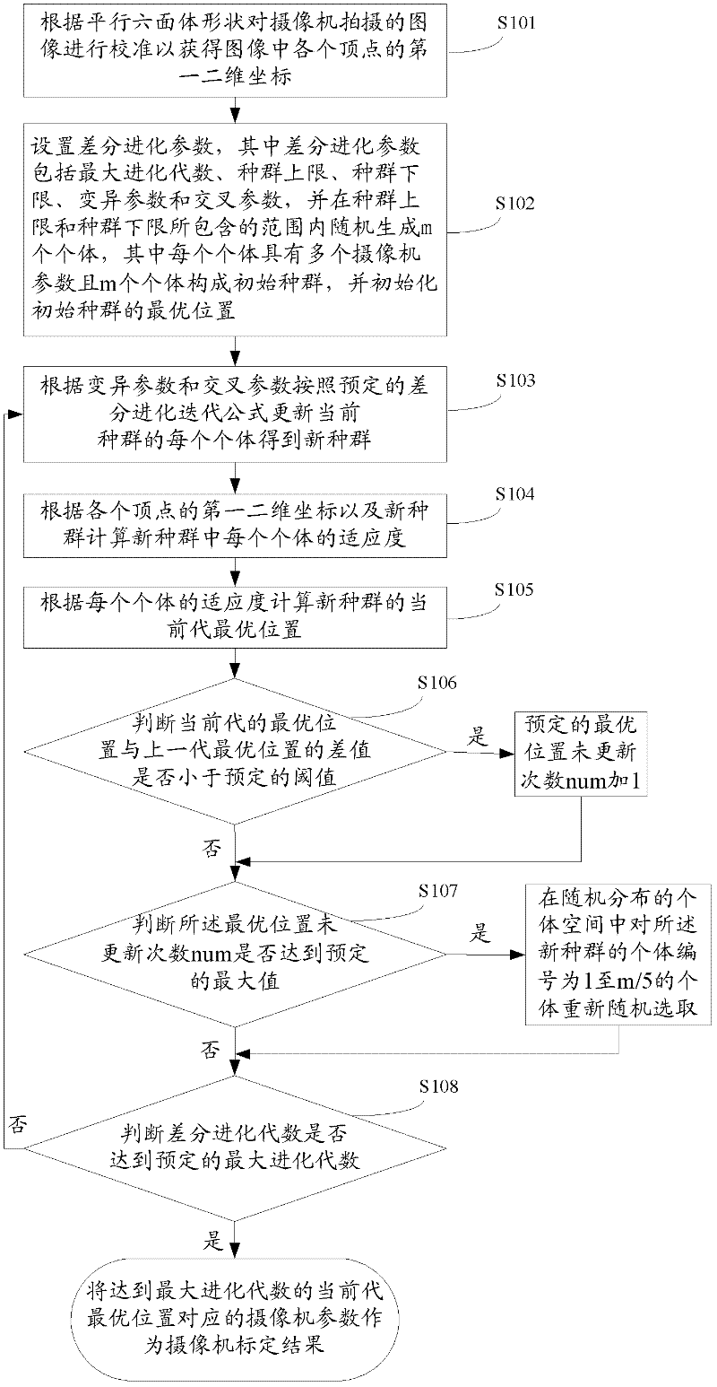
[0028] figure 1 It is a flow chart of a camera calibration method according to an embodiment of the present invention. like figure 1 As shown, the camera calibration method according to the embodiment of the present invention includes the following steps:

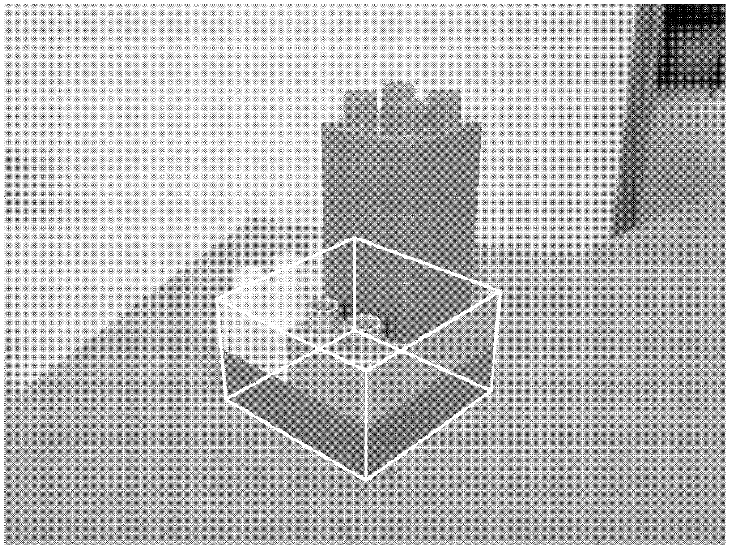
[0029] Step S101, calibrate the image captured by the camera according to the shape of the parallelepiped to obtain the first two-dimensional coordinates of each vertex in the image.

[0030] Specifically, first, manually mark each vertex of the parallelepiped appearing in the imag...


PUM


Abstract

The invention provides a calibration method of a camera. The method comprises the following steps: S1. calibrating and acquiring a one-dimensional coordinate and a two-dimensional coordinate of each vertex of an image for the shoot image; S2. setting differential evolution parameters and initializing the population; S3. updating the current population individuals and acquiring a new population; S4. calculating the fitness of the individuals of the new population according to the one-dimensional coordinate and the two-dimensional coordinate; S5. calculating the current generation optimal position of the new population according to the fitness; S6. adding 1 for the non-updated times num of the optimal position if the difference value between the optimal position of the current generation and the optimal position of the previous generation is less than the threshold; S7. selecting randomly the individuals with the individual serial number 1 to m/5 in an individual space which distributes randomly again; S8. executing the step S3 to S7 repeatedly if the differential evolution generations do not reach the maximal evolution generations, or taking the camera parameters corresponding to the current optimal position which reaches the optimal evolution generations as a calibration result of the camera. Through the method provided by the invention, the system error can be reduced, the stability is good, and the anti-interference capability is high.

Description

technical field [0001] The invention relates to the technical field of computer vision, in particular to a camera calibration method. Background technique [0002] One of the basic tasks of computer vision is to calculate the geometric information of the object in the three-dimensional space from the image information obtained by the camera, and then reconstruct and recognize the object. The interrelationship between is determined by the geometric model of camera imaging, the parameters of these geometric models are camera parameters, and the process of calculating these parameters is called camera calibration. [0003] In the prior art, the commonly used camera calibration method mostly utilizes certain inherent properties and relations in the imaging geometry to obtain some parameters first, and then uses these obtained parameters to solve other parameters, commonly known as the two-step method, the prior art The problem is that the result of the parameter in the first st...

Claims


Application Information

Patent Timeline
Patent Type & Authority Applications(China)
IPC IPC(8): G06T7/00G06T7/80
Inventor 戴琼海高浩
Owner TSINGHUA UNIV
Why Eureka
Try Eureka