Light-emitting diode driving system and circuit thereof

A technology of light-emitting diodes and driving circuits, which is applied to the layout of electric lamp circuits, light sources, electric light sources, etc., and can solve problems such as heat loss of driving circuits, insufficient brightness of light-emitting diode groups, and consumption

Inactive Publication Date: 2012-03-14
STARCHIPS TECH
View PDF5 Cites 13 Cited by
  • Summary
  • Abstract
  • Description
  • Claims
  • Application Information

AI Technical Summary

Problems solved by technology

If the supply voltage is greater than the voltage required by the drive circuit and LED groups, the excess voltage will be consumed to the drive circuit, causing heat loss in the drive circuit
Conversely, if the fixed voltage is lower than the voltage required by the driving circuit and the plurality of LED groups, the brightness of these LED groups will be insufficient, or even unable to be lit.

Method used


Image

  • Light-emitting diode driving system and circuit thereof
  • Light-emitting diode driving system and circuit thereof
  • Light-emitting diode driving system and circuit thereof

Examples


Embodiment Construction

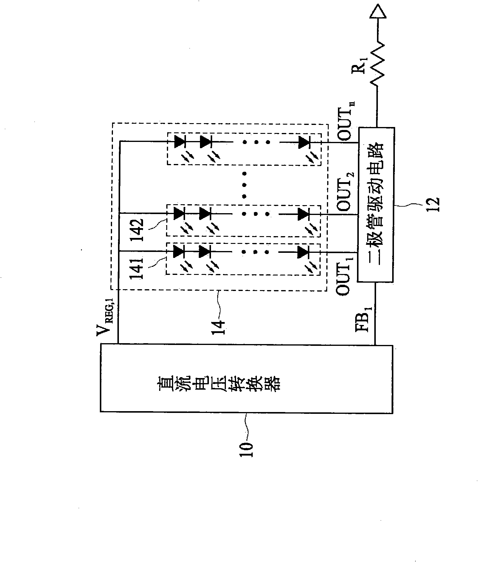
[0073] figure 1 A schematic structural diagram of an LED driving circuit 12 incorporating a DC voltage converter 10 according to an embodiment of the present invention is shown. The LED driving circuit 12 is used to control the operation of the DC voltage converter 10 so that the DC voltage converter 10 outputs a regulated DC voltage V REG,1 To an input terminal of an LED array 14 . In this embodiment, the DC voltage converter 10 is a switching regulator, which is used to generate a higher output voltage from an input power source, such as a battery, to supply the LED array 14 . refer to figure 1 , the LED array 14 is composed of a plurality of LED groups 141 and 142, wherein each LED group is composed of a plurality of LEDs connected in series. The LED driving circuit 12 is configured to provide a plurality of fixed current sources (not shown) to corresponding LED groups.

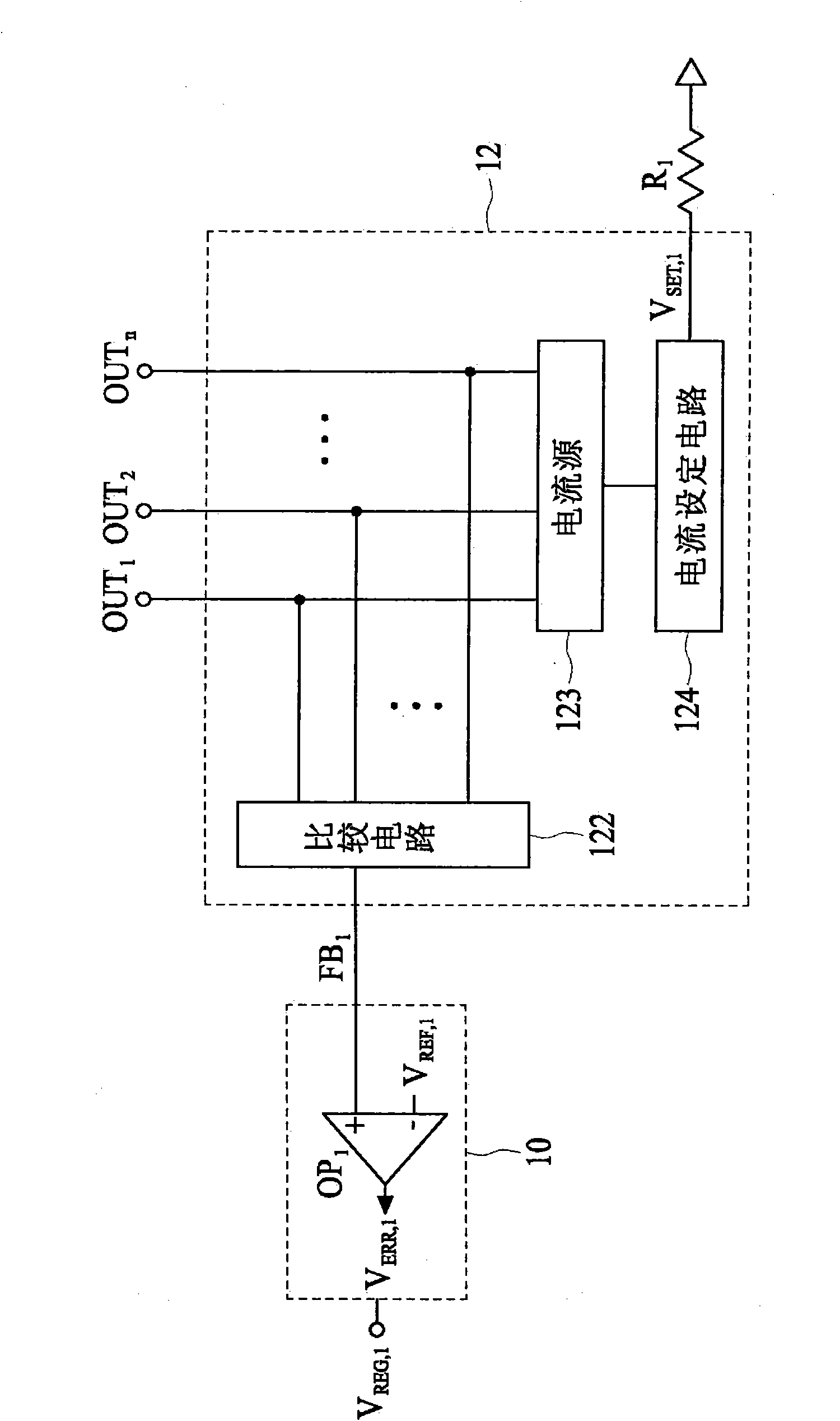
[0074] refer to figure 2 , the LED driving circuit 12 includes a comparison circuit 122 and a cur...


PUM


Abstract

The invention discloses a light-emitting diode driving system and a circuit thereof for controlling a direct current voltage converter to provide a regulated output voltage to the input end of a light-emitting diode array, wherein the light-emitting diode array consists of a plurality of light-emitting diodes. In one embodiment, the light-emitting diode driving circuit comprises a plurality of current sources, a comparison circuit and a current setting circuit. The current sources are connected to the outputs ends of the light-emitting diode array and are constructed to provide currents passing through light-emitting diode groups respectively. The comparison circuit is connected to the plurality of output ends of the light-emitting diode array, and is constructed to produce a digital or analogue signal which represents the voltage supply state of the light-emitting diode array. In addition, the construction of the current setting circuit is to set the current values of the fixed current sources. The direct current converter regulates output voltages according to feedback signals.

Description

technical field [0001] The invention relates to a light emitting diode driving system and its circuit. Background technique [0002] With the wide application of liquid crystal displays (LCDs) in televisions, monitors, notebook computers, mobile phones, PDAs (Personal Digital Assistants) and other electronic products, the demand for backlight modules for liquid crystal display lighting is increasing day by day. Among them, due to the advantages of low power consumption, high brightness, small size and long service life of light-emitting diodes, most of the backlight modules for liquid crystal display lighting now use light-emitting diodes as light sources. [0003] When light-emitting diodes are used in a backlight module, the light-emitting diodes are usually configured as a group of light-emitting diodes connected in series, known in the technical field as "LED chains", "LED sets" or "LED sets". Diode library (LED banks)" called. In order to light up the LEDs and make th...

Claims


Application Information

Patent Timeline
Patent Type & Authority Applications(China)
IPC IPC(8): G09G3/34G09G3/36H05B37/02
Inventor 许祥麟沈恩良沈志哲
Owner STARCHIPS TECH
Why Eureka
Try Eureka