
Switchgear

A switchgear and switch area technology, applied in the direction of electric switch, switchgear setting, switchgear, etc., can solve the problem of dust mixing, and achieve the effect of preventing dust mixing and condensation

Inactive Publication Date: 2012-03-14
HITACHI IND EQUIP SYST CO LTD
View PDF5 Cites 7 Cited by
  • Summary
  • Abstract
  • Description
  • Claims
  • Application Information

AI Technical Summary

Problems solved by technology

Therefore, in order to ensure the reliability of the device, there is a problem that it is necessary to prevent the dust from being mixed into the disconnection part and the occurrence of condensation.

Method used


Image

  • Switchgear
  • Switchgear
  • Switchgear

Examples


Embodiment Construction

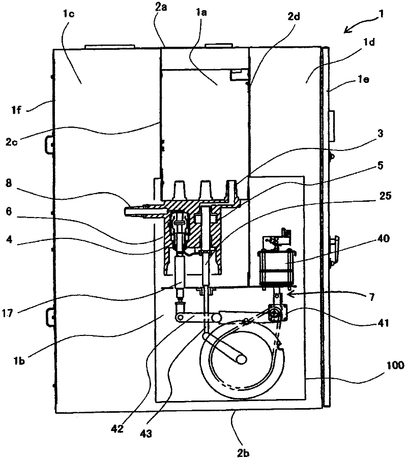
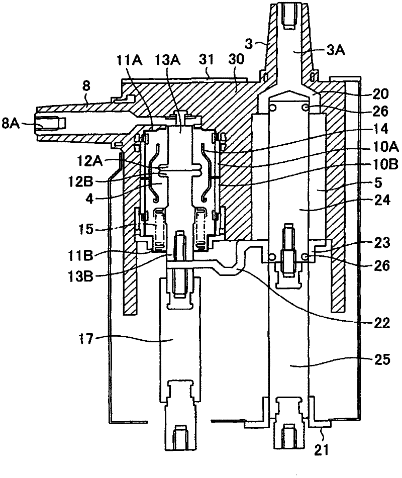
[0028] Next, one embodiment of the switchgear of the present invention will be described with reference to the drawings.

[0029] figure 1 and figure 2 is a diagram showing an embodiment of the switchgear of the present invention, figure 1 is a partial sectional side view showing one embodiment of the switchgear of the present invention, figure 2 It is a front cross-sectional view showing a switch unit constituting one embodiment of the switchgear of the present invention, and is a view showing an on state.

[0030] exist figure 1 Among them, the cabinet 1 of the switchgear is divided into a busbar area 1a, a switch area 1b, a cable area 1c, and a control area 1d by grounding metal plates arranged inside. In addition, on the front side of the chassis 1 ( figure 1 The right side of the cabinet 1) is provided with a front door 1e that can be opened on one side, and on the back side of the cabinet 1 ( figure 1 The left side) is provided with a detachable rear side panel 1...


PUM


Abstract

A switchgear includes a chassis (1) which is partitioned by metal earthed plates (2) and includes a bus bar section (1a) located at a central portion, a switch section (1b) located below the bus bar section (1a), a cable section (1c) located at a rear surface side, and a control section (1d) located at a front surface side; an air-insulated earthed disconnecting switch (5) provided in the switch section (1b); and a manipulating device (7). The switch section (1b) is separable from the chassis (1), and is configured as a case (100) having a semi-closed structure which allows air to pass therethrough but prevents particles of oil and water from passing therethrough.

Description

technical field [0001] The present invention relates to a switchgear provided with a gas-grounded disconnection unit for grounding and disconnection through gas insulation. Background technique [0002] The power distribution equipment is equipped with vacuum breakers for cutting off load current or accident current, circuit breakers and grounding switches for ensuring the safety of operators during load maintenance and inspection, and system voltage or system current. detection devices, and enclosed switchboards (called switchgear) for protective relays, etc. [0003] Among such switchgears, there is a combined type gas insulated switchgear, which is equipped with a three-position grounding breaker and a vacuum valve in which the contact is a rotor in a metal container, and SF6 gas used as an insulating gas The inside of the metal container is filled (see, for example, Patent Document 1). [0004] patent documents [0005] Patent Document 1: Japanese Patent Application L...

Claims


Application Information

Patent Timeline
Patent Type & Authority Applications(China)
IPC IPC(8): H02B13/035H02B13/075
CPCH02B1/56H02B13/01H02B13/045H01H33/66207
Inventor 高桥惠一土屋贤治森田步小林将人菅井大介
Owner HITACHI IND EQUIP SYST CO LTD
Learn More