Optimal configuration and operation method for reactive compensation of wind farm

An operation method and technology of optimized configuration, applied in reactive power compensation, reactive power adjustment/elimination/compensation, wind power generation, etc., can solve the difficulty in meeting the economic and technical requirements of reactive power compensation in wind farms, and restrict the dynamic reactive power compensation device. Practical use, high cost of dynamic reactive power compensation devices, to meet economic and technical needs, reasonable design, and reduce equipment investment.

Active Publication Date: 2012-03-14
STATE GRID SHANDONG ELECTRIC POWER COMPANY WEIFANG POWER SUPPLY +1
View PDF3 Cites 24 Cited by
  • Summary
  • Abstract
  • Description
  • Claims
  • Application Information

AI Technical Summary

Problems solved by technology

[0003] One is to invest static capacitor action compensation in the wind farm, so that the accumulated reactive power meets the requirements of the grid company. The problem with this method is that during the operation of the wind farm, due to the characteristics of the switching action of the capacitor, it cannot follow the wind farm well. The demand for reactive power changes makes the reactive power exceed the specified requirements in some time; the second is to invest a large number of dynamic reactive power compensation devices in the wind farm, such as SVC or STATCOM, etc. This method can meet the reactive power of the wind farm. However, the cost of dynamic reactive power compensation device is relatively high, and the economy is poor, which restricts the actual use of dynamic reactive power compensation device
[0004] To sum up, the existing reactive power compensation methods have different problems, and it is difficult to meet the economic and technical needs of wind farm reactive power compensation.

Method used


Image

  • Optimal configuration and operation method for reactive compensation of wind farm
  • Optimal configuration and operation method for reactive compensation of wind farm
  • Optimal configuration and operation method for reactive compensation of wind farm

Examples


Embodiment Construction

[0042] Embodiments of the present invention are described in further detail below in conjunction with the accompanying drawings:

[0043] A wind farm reactive power compensation optimization configuration and operation method, by analyzing the reactive power output characteristics of the wind farm, installing a reactive power compensation device in the wind farm and configuring the capacity of the reactive power compensation device, the static reactive power in the wind farm The switching control of compensation and dynamic reactive power compensation realizes the combined operation function of static reactive power compensation and dynamic reactive power compensation of wind farms.

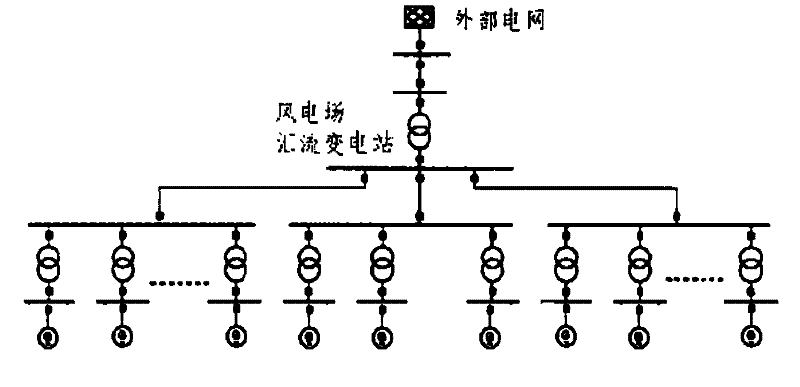
[0044] now with figure 1 A typical wind farm is shown as an example for illustration. This typical wind farm consists of 33 1.5MW wind turbines, of which every 11 wind turbines are divided into 3 groups, with a total installed capacity of 49.5MW. Each wind turbine is boosted to 35kV through a 0...


PUM


Abstract

The invention relates to an optimal configuration and operation method for reactive compensation of a wind farm. The optimal configuration and operation method is characterized by comprising the following steps of: (1) analyzing the reactive output characteristics of the wind farm, and installing a reactive compensation device in the wind farm and configuring a volume for the reactive compensation device; and (2) detecting reactive powers of a fan outlet and an interconnection point of the wind farm, and mechanically controlling the static reactive compensation and the dynamic reactive compensation of the wind farm. The optimal configuration and operation method is designed reasonably, the combination operation of the static reactive compensation and the dynamic reactive compensation of the wind farm is realized, and the reactive powers of the wind farm and a power grid are ensured under the optimal condition of the reactive compensation device of the wind farm, therefore the effect of maintaining power grid stabilization is achieved, the reactive compensation property of the wind farm is improved, the reactive compensation equipment investment is reduced, and the reactive compensation economic and technological requirements of the wind farm are satisfied.

Description

technical field [0001] The invention belongs to the field of wind power generation, in particular to a reactive power compensation optimization configuration and operation method of a wind farm. Background technique [0002] With the reduction of conventional energy sources, wind power generation has gradually become an imperative development trend. However, as an intermittent energy source, wind energy is greatly affected by the environment. Due to changes in wind speed and other environmental factors, the active power and reactive power of the wind farm will change accordingly, so that the wind turbine will absorb a large amount of reactive power during operation. , the change of reactive power will cause voltage fluctuation in the grid, even affect the voltage stability of the grid, and increase the network loss of the regional grid. At present, wind farms mainly adopt the following two reactive power compensation methods: [0003] One is to invest static capacitor acti...

Claims


Application Information

Patent Timeline
Patent Type & Authority Applications(China)
IPC IPC(8): H02J3/18
CPCY02E10/76Y02E40/30
Inventor 孙爱民张源超葛少云申刚刘中胜林勇吴金玉刘贯红陈晓东王涛王君安廖承民
Owner STATE GRID SHANDONG ELECTRIC POWER COMPANY WEIFANG POWER SUPPLY
Why Eureka
Try Eureka