Server machine cabinet and liquid-cooled radiating system thereof

A server cabinet, liquid cooling technology, applied in the field of server cabinets, can solve the problems of difficult heat dissipation, affecting the stability and security of servers, etc., to achieve the effect of improving stability and security, and good heat dissipation effect

Inactive Publication Date: 2012-03-14
HONG FU JIN PRECISION IND (SHENZHEN) CO LTD +1
6 Cites 26 Cited by

AI-Extracted Technical Summary

Problems solved by technology

However, the server will generate a lot of heat during operation, and the servers are usually stacked densely in t...

Method used

Please refer to Fig. 3 again, during work, the heat that these servers 40 produce is absorbed by this heat conducting plate 24, then transfers to this heat spreader 51, and is carried out by the working liquid in this pipeline 53 and refrigerator 52 heat exchange. The heat generated by these servers 40 forms a heat flow in the casing 30, and the heat flow is cooled to form a cold flow at the heat conducting plate 24, that is, the heat transfer device 51, and the cold flow flows to the servers 40, and exchanges heat with the heat flow gen...

Abstract

The invention discloses a server machine cabinet. The server machine cabinet comprises a shell, a server and a liquid-cooled radiating system, wherein the server and the liquid-cooled radiating system are arranged in the shell; a heat conducting plate close to the server is arranged in the shell; the liquid-cooled radiating system comprises a refrigerator and a pipeline, wherein the refrigerator is arranged out of the shell; the pipeline connects the heat conducting plate with the refrigerator; the heat generated by the server in working forms a heat flow in the shell; the heat flow is cooled at the heat conducting plate; and the pipeline is extended out of the shell and is connected with the two opposite ends of the refrigerator respectively so as to transfer the heat, absorbed from the server, of the heat conducting plate to the refrigerator to perform heat exchange. In the server machine cabinet, cold-and-hot internal circulation is formed in the shell, so that the server machine cabinet contributes to reducing heat exchange space in the shell and increasing a radiating effect; therefore, the stability and the safety of server operation are improved.

Application Domain

Technology Topic

Image

  • Server machine cabinet and liquid-cooled radiating system thereof
  • Server machine cabinet and liquid-cooled radiating system thereof
  • Server machine cabinet and liquid-cooled radiating system thereof

Examples

  • Experimental program(1)

Example Embodiment

[0031] The present invention will be further described below with reference to the drawings and embodiments.
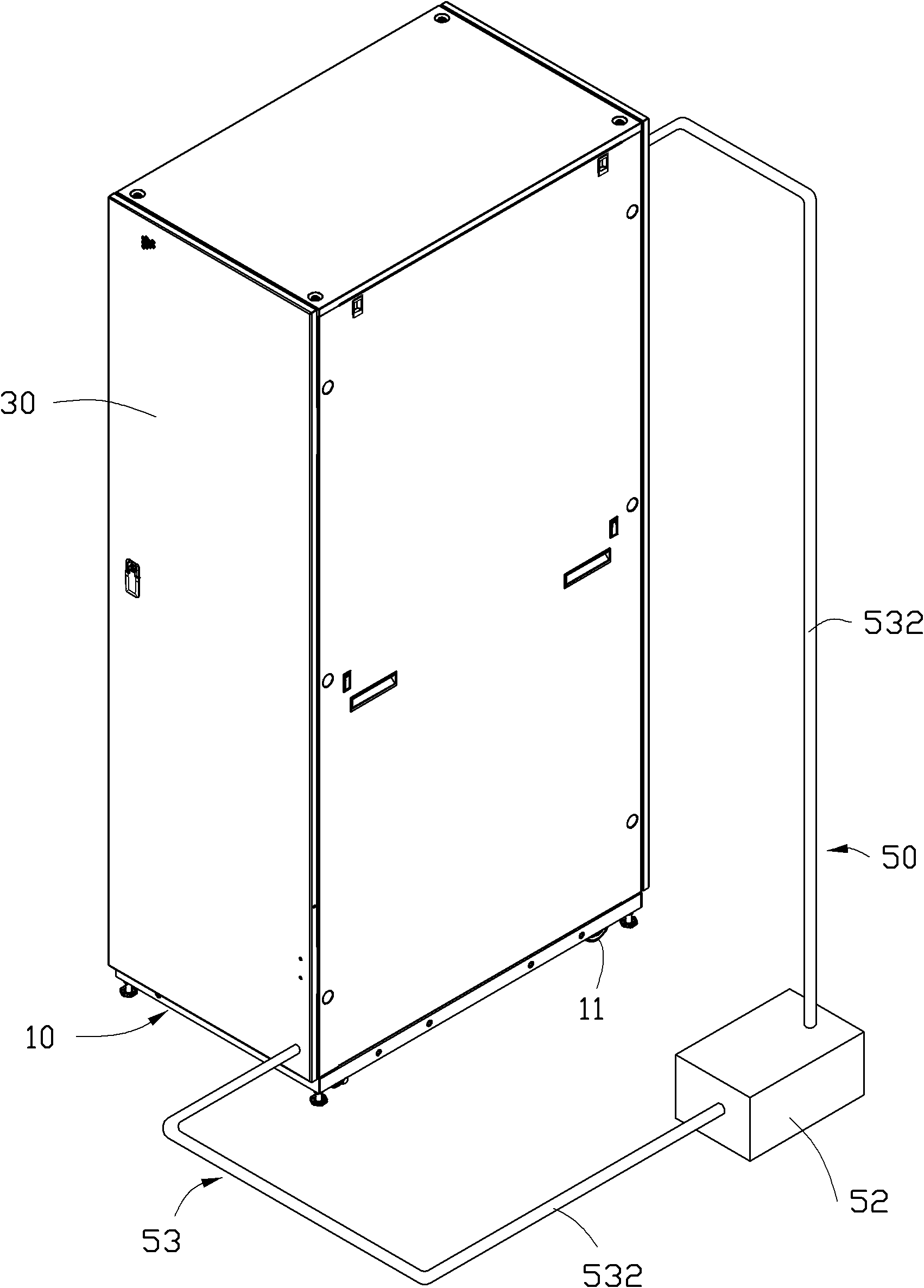
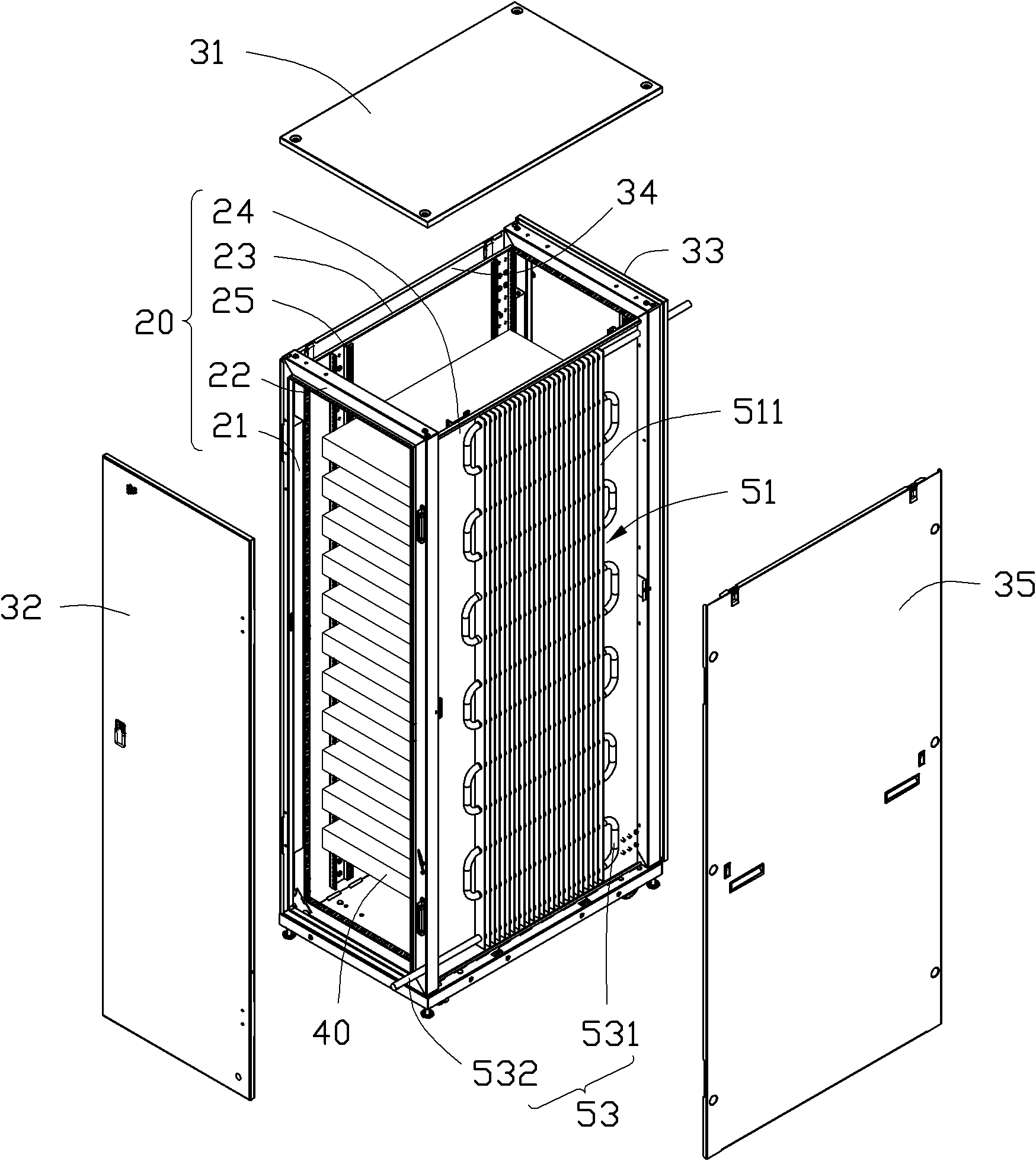
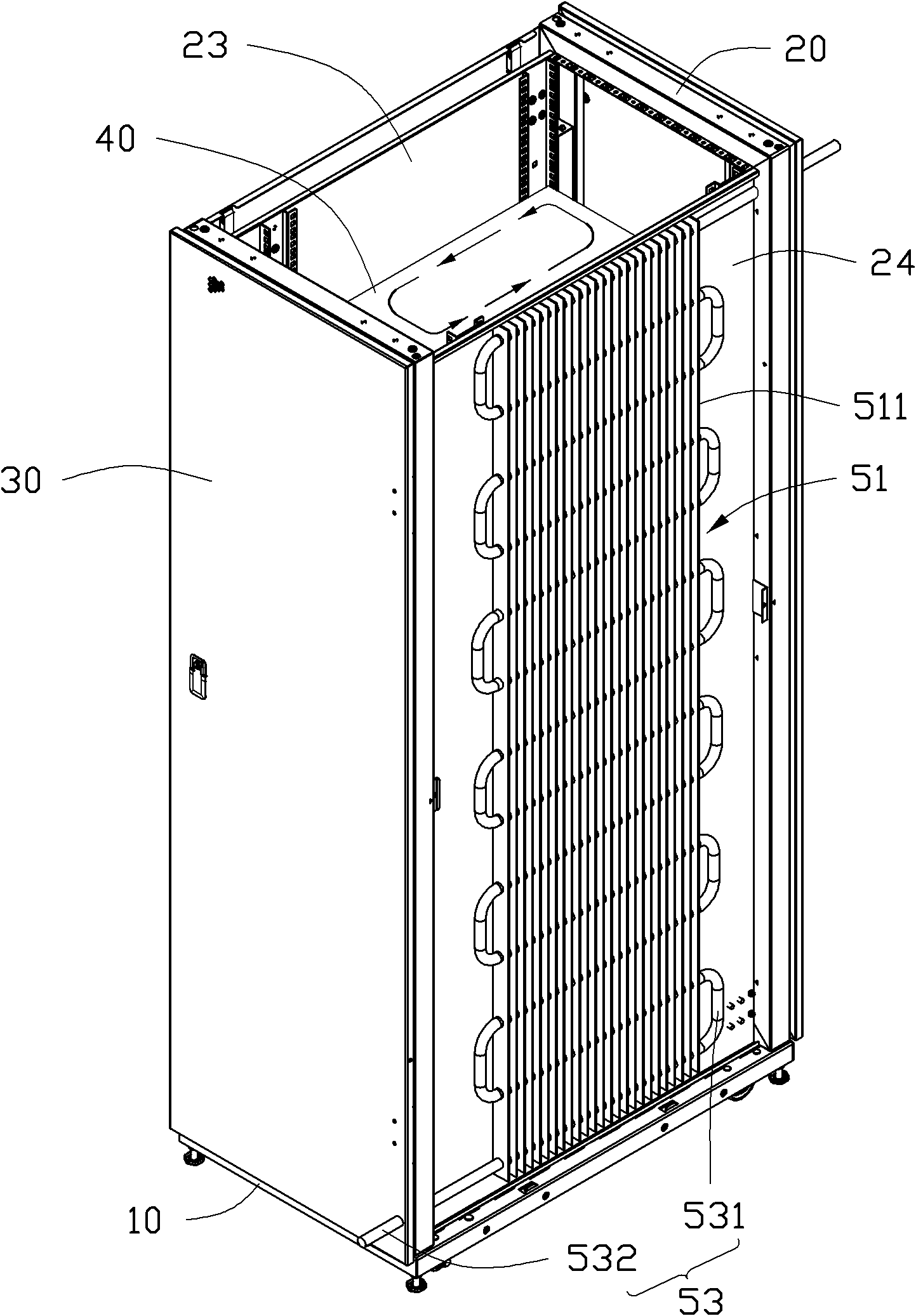
[0032] Figure 1 to Figure 2 Shown is a server cabinet according to a preferred embodiment of the present invention. The server cabinet includes a base 10, a rack 20 provided on the base 10, a housing 30 provided on the periphery of the rack 20, and installed on the machine. A number of servers 40 on the rack 20 and a liquid cooling system 50 for dissipating heat of these servers 40.
[0033] The base 10 is roughly rectangular, and a number of rollers 11 are installed at the bottom to facilitate the movement of the server cabinet.
[0034] The frame 20 is fixed on the base 10 and includes a plurality of uprights 21, a plurality of beams 22, two heat conducting plates 23 and 24 and two pairs of sliding rails 25. These uprights 21 and beams 22 together form a cube frame shape. The two heat-conducting plates 23, 24 are respectively arranged on the left and right sides of the frame 20, and are fixed on a cubic frame composed of a column 21 and a beam 22. Each heat-conducting plate 23, 24 is made of a heat-conducting material, such as copper , Aluminum, etc. The two pairs of slide rails 25 are symmetrically fixed on the two heat conducting plates 23 and 24 respectively for installing the server 40 in the rack 20.
[0035] The housing 30 includes a top plate 31, a front plate 32, a rear plate 33, and two side plates 34, 35 respectively arranged on the top, front, rear, left and right sides of the frame 20. The two side plates 34 and 35 are respectively located outside the two heat conducting plates 23 and 24, and are arranged in parallel and spaced apart from the corresponding heat conducting plates 23 and 24. The top plate 31, the front plate 32, the rear plate 33, the side plates 34, 35 and the base 10 jointly seal the rack 20 and the server 40 therein. It should be noted here that the front side and the rear side of the present invention are opposite sides of the server cabinet in the width direction, and the left and right sides are opposite sides of the server cabinet in the thickness direction.
[0036] The servers 40 are installed on the slide rails 25 of the rack 20 from the front side of the rack 20, that is, the front plate 32 of the housing 30. The servers 40 are stacked up and down in the rack 20 at intervals. The heat-conducting plates 23 and 24 are separately arranged on opposite sides of the servers 40 and are close to the servers 40.
[0037] The liquid cooling system 50 includes a heat exchanger 51, a condenser 52, and a pipeline 53 thermally connecting the heat exchanger 51 and the refrigerator 52. Both the heat exchanger 51 and the pipeline 53 are made of materials with good thermal conductivity, such as copper and aluminum. The heat exchanger 51 is formed by stacking a plurality of fins 511 for heat transfer. The fins 511 are connected in parallel and spaced apart on the heat conducting plate 24 of the frame 20 on the right side, and are located between the heat conducting plate 24 and the housing. Between the side plates 35 of 30 is located in the housing 30. The pipeline 53 is made of materials with good thermal conductivity, such as copper, aluminum, etc. The pipeline 53 includes a heat transfer section 531 and two connecting sections 532 arranged at both ends of the heat transfer section 531. The heat transfer section 531 goes back and forth It is bent into a serpentine shape and passes through the fins 511 so as to be in thermal contact with the heat exchanger 51. The two connecting sections 532 respectively extend from the top and bottom ends of the frame 20 out of the housing 30, and are respectively communicated with opposite ends of the refrigerator 52. The refrigerator 52 is arranged outside the housing 30. In this embodiment, the refrigerator 52 adopts a conventional refrigerator form, such as a thermoelectric cooling refrigerator or a general radiator type refrigerator. Both the refrigerator 52 and the pipe 53 are filled with a working fluid with a low boiling point and high enthalpy (not shown), such as water, alcohol, etc., and the working fluid circulates in the refrigerator 52 and the pipe 53, thereby The heat absorbed by the heat transfer section 531 of the pipeline 53 is exchanged at the refrigerator 52 and then flows back to the heat transfer section 531 of the pipeline 53.
[0038] Please refer again image 3 During operation, the heat generated by the servers 40 is absorbed by the heat conducting plate 24, and then transferred to the heat exchanger 51, and heat exchange is performed through the pipeline 53 and the working fluid in the refrigerator 52. The heat generated by the servers 40 forms a heat flow in the housing 30. The heat flow is cooled at the heat-conducting plate 24, that is, the heat exchanger 51 to form a cold flow. The cold flow flows to the server 40 and exchanges heat with the heat flow generated by the server 40. The internal circulation of cold and heat is performed between every two adjacent servers 40 in the housing 30, and a good heat dissipation effect can be produced without a fan, which is conducive to reducing the heat exchange space in the housing 30 and reducing costs, and improving the stability of the operation of the server 40 Sex and safety.
[0039] Of course, in the server cabinet described above, the heat exchanger 51 of the liquid cooling system 50 can also be arranged on the heat conducting plate 23 on the left side of the rack 20 or on the heat conducting plates 23 and 24 on the left and right sides at the same time. Heat transfer device 51.

PUM

no PUM

Description & Claims & Application Information

We can also present the details of the Description, Claims and Application information to help users get a comprehensive understanding of the technical details of the patent, such as background art, summary of invention, brief description of drawings, description of embodiments, and other original content. On the other hand, users can also determine the specific scope of protection of the technology through the list of claims; as well as understand the changes in the life cycle of the technology with the presentation of the patent timeline. Login to view more.

Similar technology patents

Classification and recommendation of technical efficacy words

  • Improve stability and security
  • Good cooling effect

Wireless network connecting method of a terminal device

InactiveCN104394531AImprove stability and securityAvoid spoofing or threatening network securityTransmissionSecurity arrangementFingerprintIp address
Owner:WUXI BIOKEE BIOMETRICS TECH

Control method for diesel and stored energy coordination of intelligent micro-grid

Owner:ELECTRIC POWER RESEARCH INSTITUTE, CHINA SOUTHERN POWER GRID CO LTD

Oven

Owner:宁波优尼珂家用电器有限公司
Why Eureka
Try Eureka