
Stent conveying device

A technology for delivery devices and outer tubes, applied in stents, medical science, prostheses, etc., can solve problems such as poor positioning accuracy, and achieve the effect of enhancing and improving positioning accuracy

Inactive Publication Date: 2012-03-21
SHANGHAI MICROPORT MEDICAL (GROUP) CO LTD
View PDF5 Cites 12 Cited by
  • Summary
  • Abstract
  • Description
  • Claims
  • Application Information

AI Technical Summary

Problems solved by technology

However, the positioning accuracy of the prior art stent delivery device is relatively poor

Method used


Image

  • Stent conveying device
  • Stent conveying device
  • Stent conveying device

Examples


Embodiment Construction

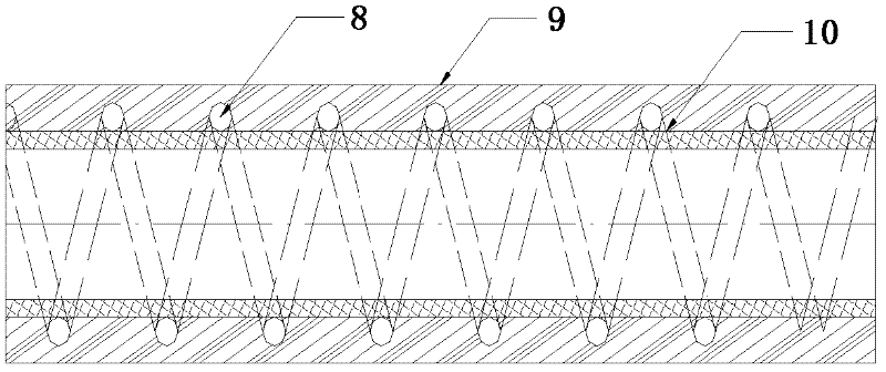
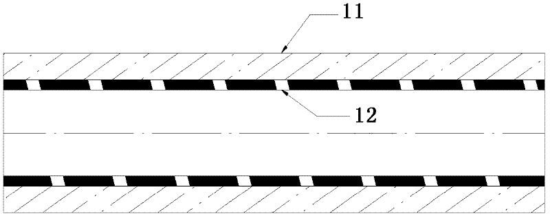
[0035] In order to enable those skilled in the art to better understand the technical solutions in the present application, the technical solutions in the embodiments of the present invention will be clearly and completely described below in conjunction with the drawings in the embodiments of the present invention. Apparently, the described embodiments are only some of the embodiments of this application, not all of them. Based on the specific embodiments described in the present application, all other embodiments obtained by persons of ordinary skill in the art without making creative efforts should fall within the scope of the present invention.

[0036] The present invention provides a stent delivery device for medical use, through which a balloon can be used to expand a blood vessel or carry a stent.

[0037] The following reference Figure 1 to Figure 7 Preferred embodiments of the present invention will be described in detail.

[0038] like figure 1 As shown, the sten...


PUM

PropertyMeasurementUnit
Lengthaaaaaaaaaa
Lengthaaaaaaaaaa

Abstract

The invention provides a stent conveying device, which comprises a connecting part, an outer tube, an inner tube and a balloon. The outer tube is connected with the balloon and the connecting part, the inner tube penetrates through the inside of the outer tube and the inside of the balloon, the connecting part is communicated with the balloon via a joint of the connecting part and through an inner cavity between the outer tube and the inner tube, the outer tube comprises a far outer tube portion and a near outer tube portion, the far outer tube portion is located at a far end of the outer tube, and the near outer tube portion is located at the near end of the outer tube. The stent conveying device is characterized in that at least one of the far outer tube portion and the near outer tube portion comprises at least two layers, and materials and structures of the at least two layers can strengthen positioning accuracy of the stent conveying device. According to the invention, an outer tube structure with the special design is provided, and accordingly, the positioning accuracy of the stent conveying device can be improved.

Description

technical field [0001] The invention relates to a stent delivery device for medical use. Background technique [0002] Most of the current domestic stent delivery devices focus on tracking, passing, and pushing. However, the coverage of collateral vessels needs to be considered during the operation of bifurcation lesions, so there is a technical problem in the correspondence between the mesh of the stent and the collateral vessels. Clinically, balloon expansion of the stent mesh is mainly used to achieve the required vessel diameter, but this method has problems such as uncontrollable expanded size and inability to position the mesh. Moreover, there is no stent delivery device specially used for bifurcation lesions in China. [0003] Patent document CN201279337 discloses a balloon dilatation catheter, which is a rapid exchange balloon catheter with a helical structure in the middle, wherein the helical part is described as follows: the helical part is provided with a helic...

Claims


Application Information

Patent Timeline
IPC IPC(8): A61F2/84A61F2/962
CPCA61F2/958A61F2230/0091
Inventor 张琳琳唐智荣罗七一
Owner SHANGHAI MICROPORT MEDICAL (GROUP) CO LTD
Learn More