
Flexible welding cutting device of workpiece with special section

A special-shaped cross-section and cutting device technology, which is applied in welding/cutting auxiliary equipment, auxiliary devices, welding equipment, etc., can solve the problems of slow groove processing speed, difficult welding, high on-site installation cost, etc., and achieves low cost and compact structure , the effect of exquisite mechanism

Inactive Publication Date: 2012-03-21
BEIJING INSTITUTE OF PETROCHEMICAL TECHNOLOGY
View PDF6 Cites 15 Cited by
  • Summary
  • Abstract
  • Description
  • Claims
  • Application Information

AI Technical Summary

Problems solved by technology

[0003] At present, the on-site installation and welding of this special-shaped cross-section expansion tube mainly has the following problems: First, the groove processing is difficult. Since the test piece is a special-shaped cross-section expansion tube, it is impossible to use conventional groove processing equipment for groove processing, and it is processed by hand. The groove processing speed is slow and the groove processing quality is low
Secondly, welding is difficult. Because its cross-section is a special-shaped cross-section, at present, on-site manual welding is generally used. It takes more than 4 hours to complete the whole process of welding a groove. The efficiency is low, the welding quality is unstable, and the on-site installation cost is high.
[0004] In addition, there are currently other engineering sites that need to perform welding and cutting of special-shaped cross-section workpieces, as well as flaw detection on the surface of special-shaped cross-section workpieces or weld seam inspection after welding, but there is no simple and easy device that can perform the above operations in China

Method used


Image

  • Flexible welding cutting device of workpiece with special section
  • Flexible welding cutting device of workpiece with special section
  • Flexible welding cutting device of workpiece with special section

Examples


Embodiment Construction

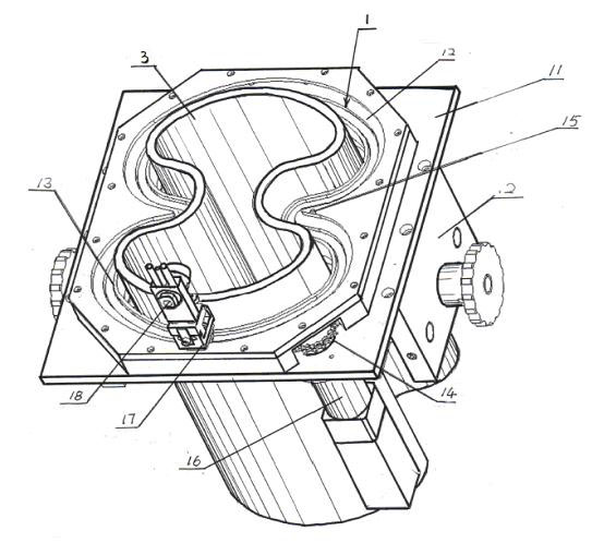
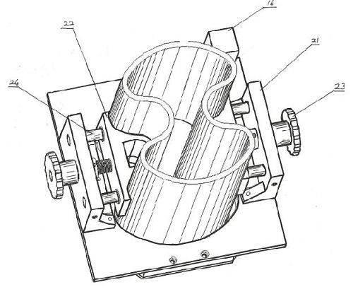
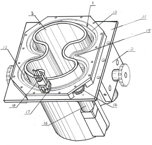
[0024] Depend on figure 1 , figure 2 As shown, a flexible welding and cutting device for special-shaped cross-section workpieces is mainly composed of a flexible transmission device 1 and a workpiece fixing device 2, wherein: the flexible transmission device 1 is composed of a base plate 11, an annular guide rail 12, a transmission chain 13, a transmission sprocket 14, a press wheel 15, transmission motor 16 and welding torch support frame 17; on the base plate 11 is fixed an annular guide rail 12, the transmission chain 13 is embedded in the annular guide rail 12, the transmission motor 16 is arranged below the base plate 11, and drives the transmission sprocket above the base plate 11 14. There are two pressure wheels 15 on the sides of the two depressions in the section of the workpiece 3 to compress the transmission chain 13, which are used to compress the transmission chain 13. The lower end is fixed on the base plate 11, and the bottom of the welding torch support frame...


PUM


Abstract

The invention relates to a flexible welding cutting device of a workpiece with a special section, mainly comprising a flexible transmission device (1) and a workpiece fixing device (2), wherein a ring-shaped guide rail (12) is fixed on a base plate (11), a transmission chain (13) is embedded on the base plate (11), and a transmission motor (16) is arranged under the base plate (11) and can drive a transmission chain wheel(14); the concave positions of the workpiece (3) are provided with pressing wheels (15) for pressing the transmission chain (13); a welding gun supporting frame (17) is connected with the transmission chain (13) and can move along with the transmission chain (13); and a pressing static plate (21) is fixed under the base plate (11) and the workpiece (3) can be fixed tightly by a pressing movable plate (22) through a pressing knob (23). The flexible welding cutting device can carry out flexible profiling on the workpiece with the special section, is applicable to cutting of the workpieces with various special sections, the flaw detection of the surfaces of the workpieces and detection of welding seams, and is simple in structure and low in cost, and simple and easy in use, repair and maintenance.

Description

technical field [0001] The invention relates to a welding and cutting device, in particular to a flexible welding and cutting device for special-shaped cross-section workpieces. Background technique [0002] In oilfield wellhead engineering, special-shaped cross-section expansion pipe welding is required. After the expansion tube with special-shaped cross-section is prefabricated, it needs to be assembled, welded and tested on site. After the weld seam inspection of a section of connecting pipe is qualified, the connected pipe is driven into the ground, and then the next section of pipe is welded and spliced ​​until the required design length is reached. [0003] At present, the on-site installation and welding of this special-shaped cross-section expansion tube mainly has the following problems: First, the groove processing is difficult. Since the test piece is a special-shaped cross-section expansion tube, it is impossible to use conventional groove processing equipment f...

Claims


Application Information

Patent Timeline
IPC IPC(8): B23K37/00
Inventor 薛龙韩玉光邹勇曹莹瑜
Owner BEIJING INSTITUTE OF PETROCHEMICAL TECHNOLOGY
Learn More