

Clamp special for flat turbine head end face
A special fixture and turbine head technology, which is applied in the field of turbine manufacturing, can solve the problems of rough machining surface, large center runout of machined parts, and reduced processing efficiency, and achieve the effect of smooth machining surface, small center runout and high processing efficiency
Inactive Publication Date: 2012-03-21
WUXI MINGZHU TURBOCHARGER MFG
View PDF0 Cites 1 Cited by
- Summary
- Abstract
- Description
- Claims
- Application Information
AI Technical Summary
Problems solved by technology
[0004] However, in production, it was found that due to the special material and strong cutting force, the clamping position of the three-jaw chuck could not meet the clamping requirements, resulting in reduced processing efficiency, rough processed surface, easy chipping, and large center runout of the processed parts.
Method used
View moreImage
Smart ImageViewing Examples

Examples
Embodiment Construction
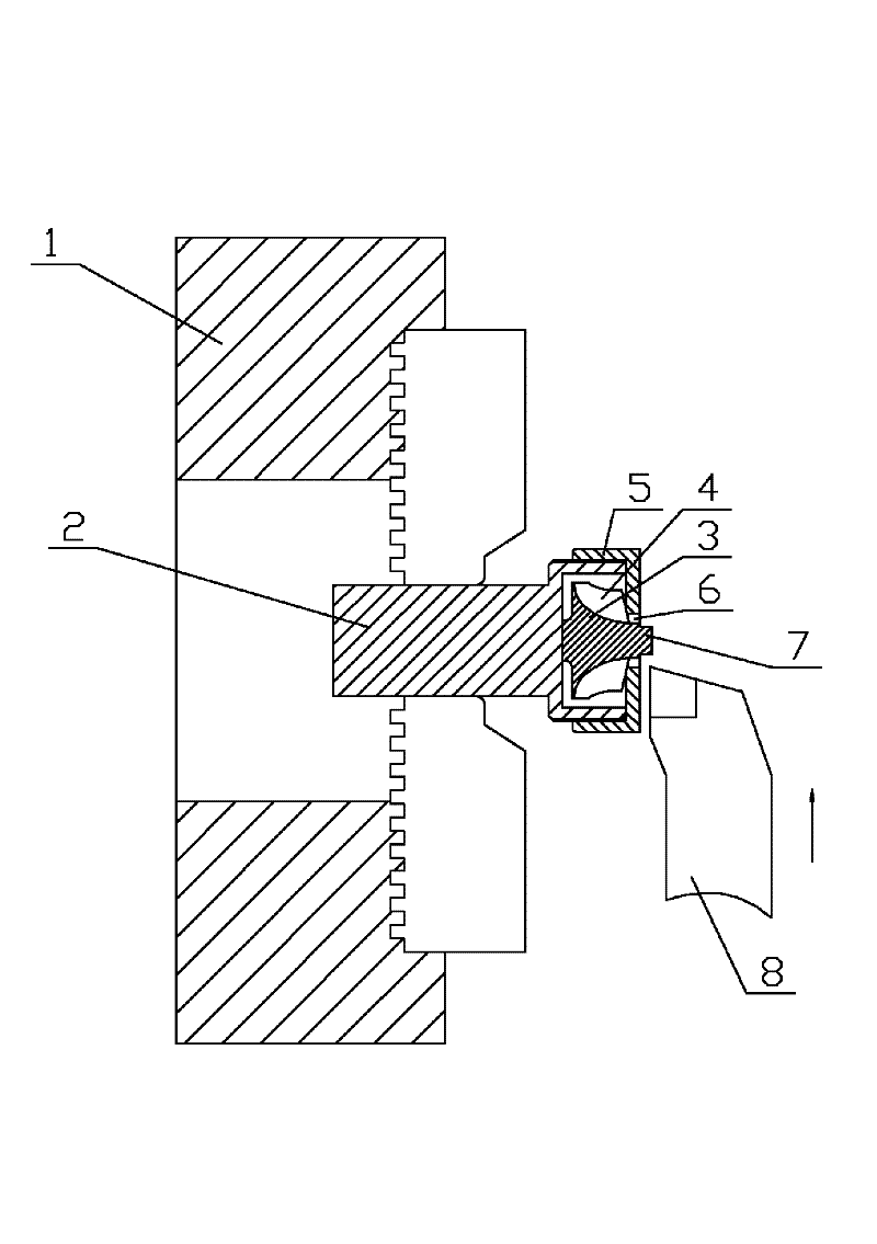
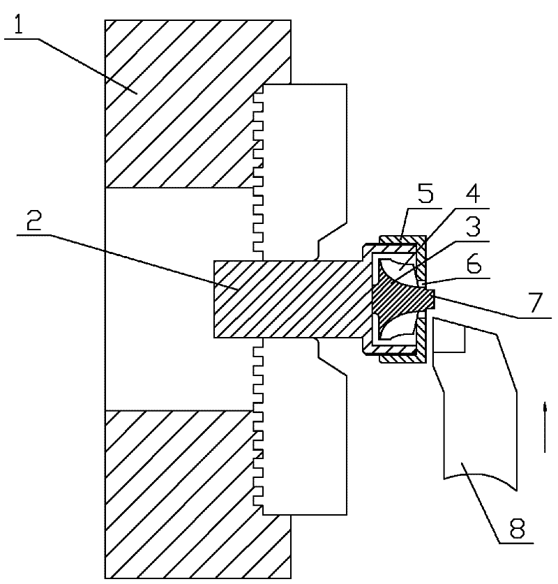
[0010] See figure 1 , which includes a three-jaw chuck 1, a base 2, and a flat turbine 3. The upper part of the base 2 is provided with an open cavity 4, the flat turbine 3 is installed inside the cavity 4, and the end cover 5 is installed outside the cavity 4. The end face, the end cover 5 is provided with a central hole 6, the head end face 7 of the flat turbine 2 is exposed to the center hole 6 of the end cover 5, the outer circumference of the worm wheel of the flat turbine 2 fits the inner end surface of the cavity 4, and the base 2 is specifically The cylindrical structure, the three-jaw chuck 1 clamps the outer circular surface of the base 2 . figure 1 Among them, 8 is a tool.
Login to View More PUM
 Abstract
The invention provides a clamp special for a flat turbine head end face. By using the clamp, the clamping positioning of a three-jaw chuck meets a clamping requirement, the machining efficiency is high, a machined surface is smooth, a fracture phenomenon is not easy to cause, and the centre beat of a machined component is low. The clamp special for the flat turbine head end face comprises the three-jaw chuck, a base and a flat turbine, and is characterized in that: the upper part of the base is provided with an open cavity body; the flat turbine is arranged in the cavity body; an end cover is covered on the outer end surface of the cavity body; a centre hole is formed in the end cover; the head end surface of the flat turbine is exposed from the centre hole of the end cover; the outer circumference of a worm wheel of the flat turbine is adhered to the inner end surface of the cavity; and the three-jaw chuck clamps the outer edge surface of the base.
Description
technical field [0001] The invention relates to the technical field of turbine manufacturing, in particular to a special clamp for the end face of a flat turbine head. Background technique [0002] The working condition of the turbine is harsh, so the special material K18 is used to make it resistant to high temperature, not easy to deform, and high in strength. [0003] When processing the end face of the flat turbine head, the existing technology uses a three-jaw chuck to clamp the edge of the turbine head to fix it. [0004] However, in production, it was found that due to the special material and strong cutting force, the clamping position of the three-jaw chuck could not meet the clamping requirements, resulting in reduced processing efficiency, rough processed surface, easy chipping, and large center runout of the processed parts. Contents of the invention [0005] In view of the above problems, the present invention provides a special fixture for the flat turbi...
Claims
Login to View More Application Information
Patent Timeline
 Patent Type & AuthorityApplications(China)
IPC IPC(8): B23Q3/12
Inventor高锡民
OwnerWUXI MINGZHU TURBOCHARGER MFG