Eureka AIR delivers breakthrough ideas for toughest innovation challenges, trusted by R&D personnel around the world.

Reaction fin in front of propeller

A technology of reactive fins and propeller hubs, which is applied in the field of reactive fins in front of propellers, can solve the problems of recovery of wake uniformity and loss of rotational energy in the wake of the propeller, loss of rotational energy in the wake of the propeller, uneven wake field, etc., to achieve The effect of reducing the risk of hull vibration, uniform wake, and improving propulsion efficiency

Active Publication Date: 2013-11-27
SHANGHAI MERCHANT SHIP DESIGN & RES INST
View PDF6 Cites 0 Cited by
  • Summary
  • Abstract
  • Description
  • Claims
  • Application Information

AI Technical Summary

Problems solved by technology

Both of these two reaction fins have two fins arranged in the horizontal direction, but because the flow field of the rotating propeller behind the ship is completely asymmetrical, although the aforementioned two reaction fins can achieve a certain energy-saving effect and save power. 2% to 4%, but there are still defects in the uniformity of the wake and the loss of the rotational energy in the recovery of the propeller wake, and with the development trend of the lower part of the conventional hull tending to be enlarged, the wake field of the upper and lower parts of the stern is seriously inconsistent. Even, the loss of rotational energy in the propeller wake is serious, therefore, the existing reactive fins in front of the propeller can no longer solve the above problems

Method used


Image

  • Reaction fin in front of propeller
  • Reaction fin in front of propeller
  • Reaction fin in front of propeller

Examples


Embodiment Construction

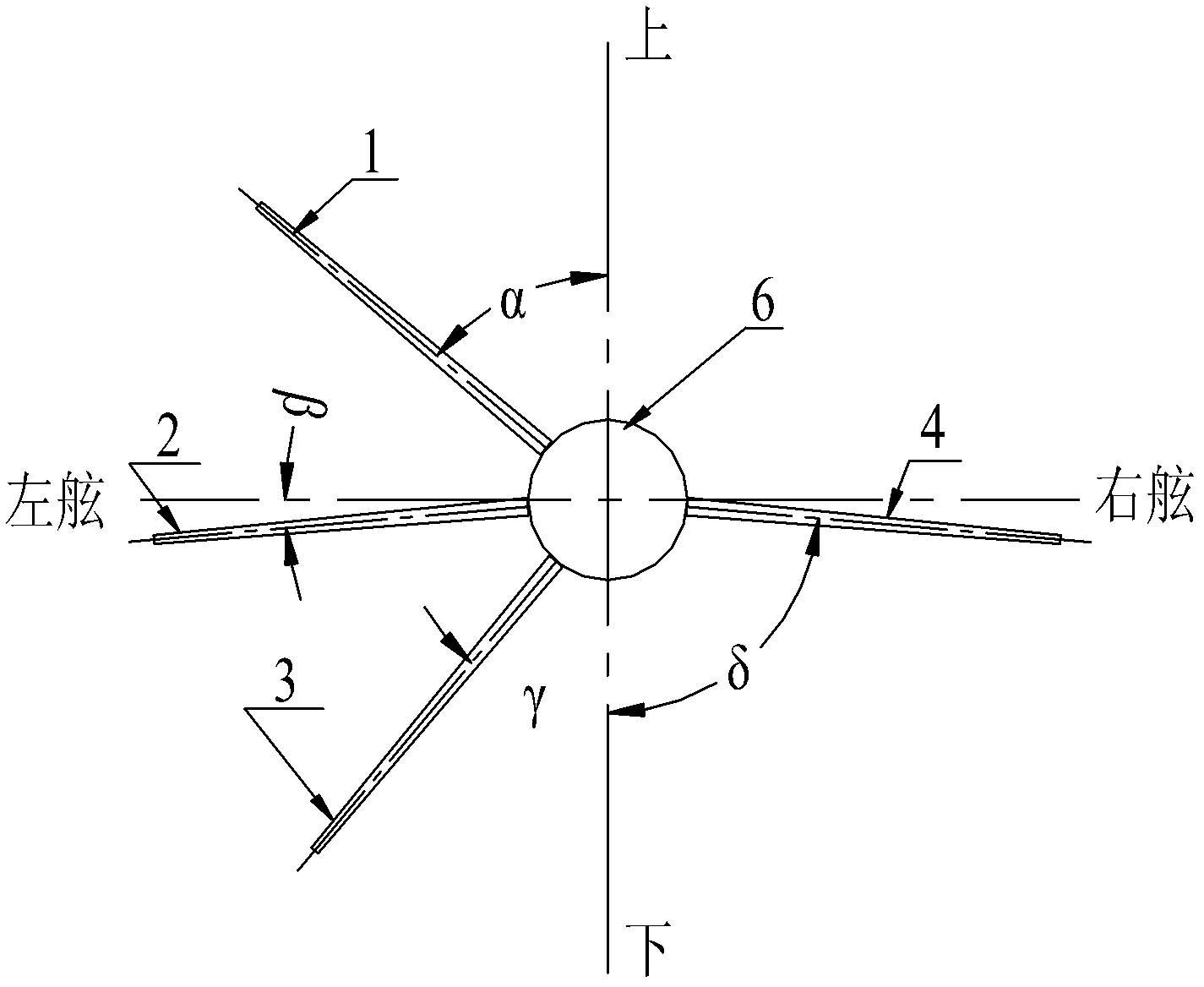
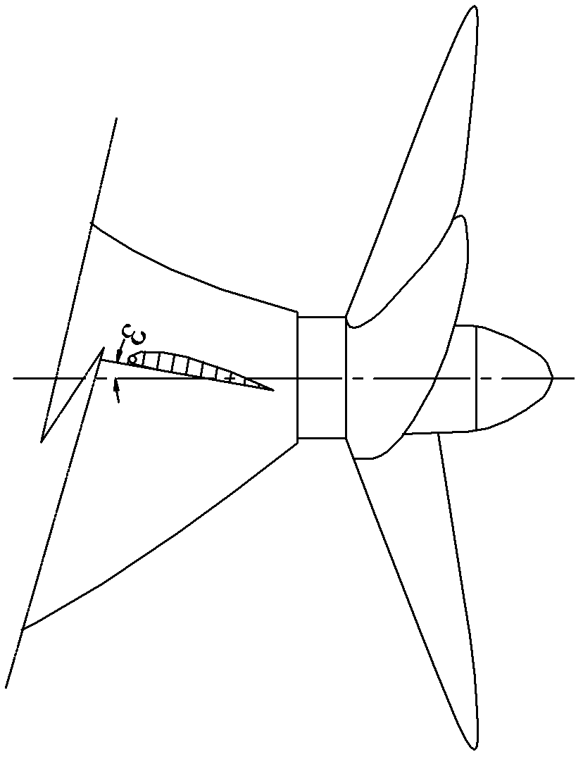
[0018] Such as figure 1 and figure 2 As shown, a kind of paddle front reaction fin, viewed from the rear side of the propeller, is provided with three fins on the stern on the left side of the longitudinal centerline of the propeller hub 6, from top to bottom are the first fin 1, the second fin 2 and The third fin 3 is provided with a fourth fin 4 on the right side, wherein the angle α between the first fin 1 and the longitudinal centerline is in the range of 46°≤α≤53°, and the second fin 2 and the horizontal direction The range of the included angle β is 1°≤β≤8°, the range of the included angle γ between the third fin 3 and the longitudinal centerline is 37°≤γ≤44°, and the range between the fourth fin 4 and the longitudinal centerline The range of the included angle δ is 82°≤δ≤89°.

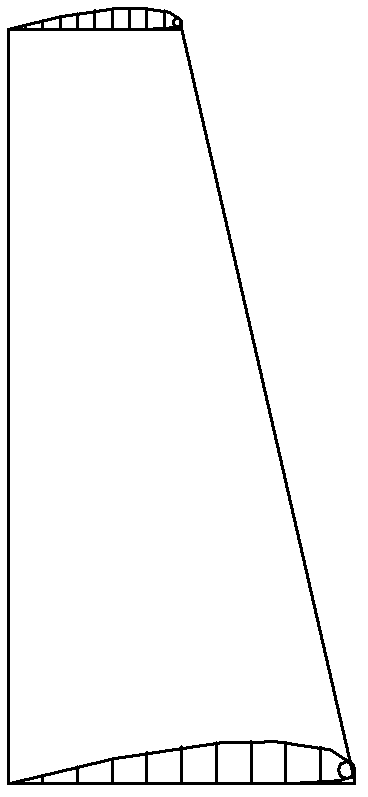
[0019] The shape of the fin is selected from the NACA airfoil with a relatively small drag-lift ratio, but attention should be paid to the overall consideration of the combination of strength ...


PUM


Abstract

The invention relates to a reaction fin in front of a propeller, which is arranged on a conventional right-handed single propeller ship, and belongs to the technical field of hull energy saving equipment. When the reaction fin in front of the propeller is seen from the rear side of the propeller, a stern at the left side of a longitudinal central line of a propeller hub (6) is provided with a first fin (1), a second fin (2) and a third fin (3) from the top to the bottom and the right side of the longitudinal central line of the propeller hub (6) is provided with a fourth fin (4), wherein an included angle alpha between the first fin and the longitudinal central line is in the range of more than or equal to 46 degrees and less than or equal to 53 degrees; an included angle beta between the second fin (2) and the horizontal direction is in the range of more than or equal to 1 degree and less than or equal to 8 degrees; an included angle chi between the third fin (3) and the longitudinal central line is in the range of more than or equal to 37 degrees and less than or equal to 44 degrees; and an included angle delta between the fourth fin (4) and the horizontal line is in the range of more than or equal to 82 degrees and less than or equal to 89 degrees. Due to the adoption of the structure, three of the four fins are distributed in a low-value region, i.e. a high-speed region, of a wake field, so that the adverse effect of the resistance of the fins on the flowing in a low-speed region is reduced, and the fins distributed in the high-speed region are also beneficial to the homogenization of wake when ensuring the wake field in front of the propeller to rotate in advance.

Description

technical field [0001] The invention relates to an oar front reaction fin, in particular to an oar front reaction fin installed on a conventional right-handed single oar boat, and belongs to the technical field of hull energy-saving equipment. Background technique [0002] Reaction Fin (R.F. for short) is a deflector installed in front of the propeller of a fat single-screw ship. Like a stationary propeller with more blades, it can reduce the rotational movement of the propeller wake, thus saving the main engine of the ship. power. The reaction fin is composed of a number of fins that form a certain angle of attack with the water flow. After the water flow passes through the fins, the original flow direction is changed to form a pre-swirling water flow that is opposite to the direction of the propeller wake, which reduces the rotation of the propeller wake. The role of energy loss, so as to achieve the purpose of energy saving. [0003] Research at home and abroad has real...

Claims


Application Information

Patent Timeline
Patent Type & Authority Patents(China)
IPC IPC(8): B63H1/28
Inventor 周志勇陈康魏菲菲林洁
Owner SHANGHAI MERCHANT SHIP DESIGN & RES INST
Why Eureka
Eureka Blog
Learn More