Planet surface landing system

A landing system and planetary technology, applied in the field of planetary landing equipment, can solve the problems of reducing rocket exhaust energy, poor landing accuracy of the landing system, and low propulsion efficiency of the landing system, and achieve the goal of improving propulsion efficiency, reducing speed, and improving utilization Effect

Active Publication Date: 2017-03-22
NAT UNIV OF DEFENSE TECH
View PDF6 Cites 11 Cited by
  • Summary
  • Abstract
  • Description
  • Claims
  • Application Information

AI Technical Summary

Problems solved by technology

[0008] In order to overcome the defects of low propulsion efficiency and poor landing accuracy of the landing system in the prior art, the present invention proposes a planetary surface landing system, which fully reduces the exhaust gas carried away by the rocket and the rotor by using the combination of the rocket and the rotor as the power. energy, and the attitude control of the aircraft can be achieved by changing the rotor speed, which can better solve the problems existing in the prior art

Method used


Image

  • Planet surface landing system
  • Planet surface landing system
  • Planet surface landing system

Examples


Embodiment Construction

[0035] The present invention will be further described below in conjunction with the accompanying drawings and specific embodiments.

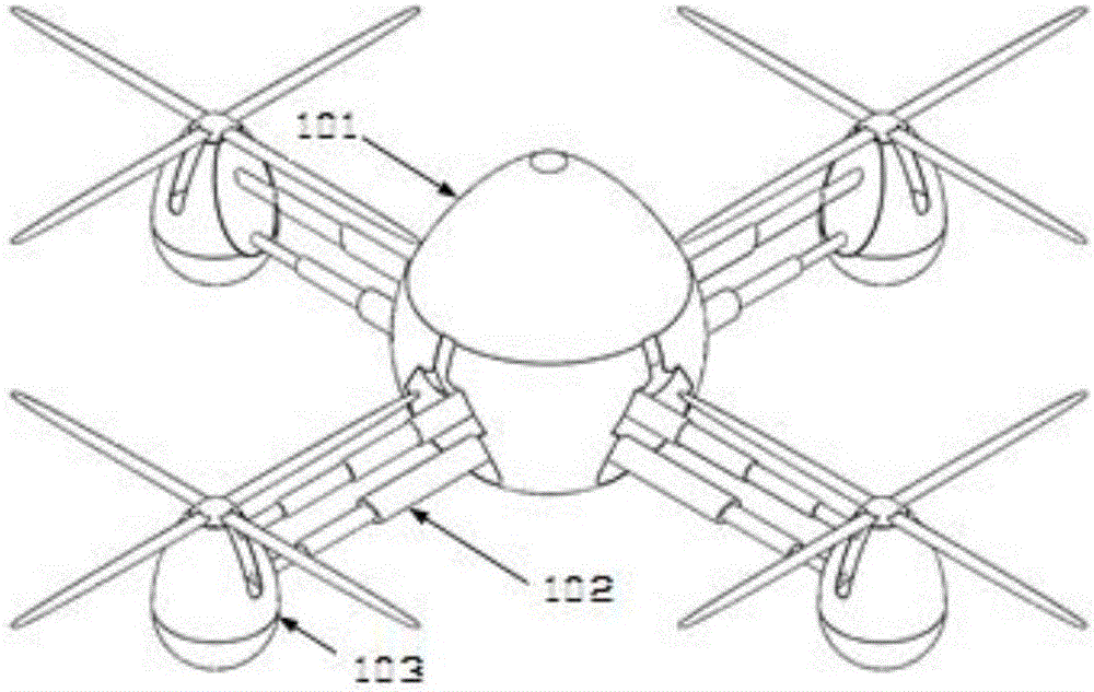
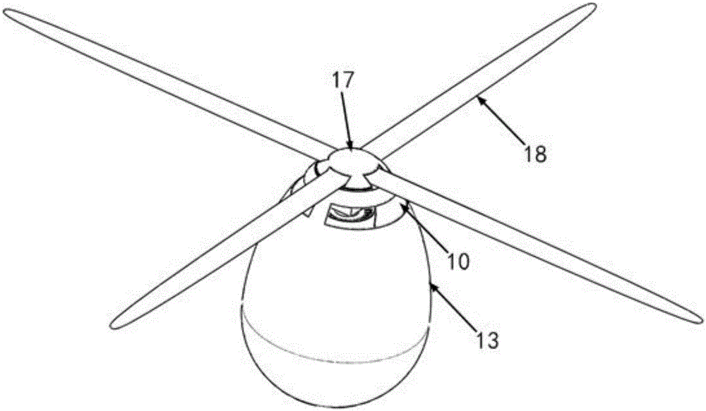
[0036] refer to figure 1 , Embodiment 1 provides a schematic structural diagram of a planetary surface landing system. A planetary surface landing system of the present invention comprises a load cabin 101, a connecting mechanism 102 and a rocket rotor combined engine 103, the load cabin 101 is used for carrying payload and storing propellant, and 4 rocket rotor combined engines 103 connect with the connecting mechanism 102 The load compartment 101 is connected. Described rocket rotor combined engine 103 comprises casing 13, rotor and the power system that is arranged in casing 13 and is used for driving rotor, and described rotor is arranged on the top of casing 13 and is connected with the power system in casing 13, and rotor is in the power system. The driven rotation generates aerodynamic lift, which provides the resistance required for t...


PUM


Abstract

A planet surface landing system comprises a loading cabin, connecting mechanisms and one or more rocket and rotor combined engines. The loading cabin is used for loading an effective load and storing a propellant. The rocket and rotor combined engines are connected with the loading cabin through the connecting mechanisms. Each rocket and rotor combined engine comprises a shell, a rotor and a power system arranged in the shell and used for driving the rotor, wherein the rotor is arranged at the top of the shell, connected with the power system in the shell, and driven by the power system to rotate to generate aerodynamic lift so as to provide resistance required for deceleration of the planet surface landing system during landing. By adjusting the rotating speeds of the rotors on the rocket and rotor combined engines, pitching, rolling and yawing motion of the whole planet surface landing system are achieved. Rockets and the rotors are combined and used as the power, and energy taken away by rocket exhaust is fully reduced; and aircraft attitude control is achieved by changing the rotating speeds of the rotors, and problems existing in the prior art can be better solved.

Description

technical field [0001] The invention belongs to the technical field of planetary landing equipment, and in particular relates to a surface landing system for a planet with an atmosphere. Background technique [0002] At present, all major aerospace countries in the world are actively carrying out planetary exploration. The United States, Europe, Russia, India and other countries have announced their own Mars exploration or lunar exploration plans, and China has also announced the launch of Mars exploration missions in 2020. Planetary landing, also known as planetary entry, descent and landing (Entry, Descent and Landing, EDL), is used to deliver payloads such as astronauts and equipment from planetary orbit to the surface of the planet. Although the time is very short, it is the most critical for planetary exploration. one of the technologies. Generally, after the Mars lander is decelerated by the parachute, the stable descent speed when approaching the surface of Mars is s...

Claims


Application Information

Patent Timeline
Patent Type & Authority Applications(China)
IPC IPC(8): B64G1/62
CPCB64G1/62
Inventor 李清廉张北辰崔朋王旭王小波胡润生刘昕晨
Owner NAT UNIV OF DEFENSE TECH
Why Eureka
Try Eureka