Unmanned aerial vehicle-mounted laser radar system
An airborne laser radar and laser radar technology, applied in the field of laser radar remote sensing surveying and mapping, can solve problems such as weak technical foundation, and achieve the effects of low operating cost, easy transportation, and less use restrictions
Inactive Publication Date: 2012-03-21
MIANYANG SKYEYE LASER TECH
View PDF2 Cites 64 Cited by
- Summary
- Abstract
- Description
- Claims
- Application Information
AI Technical Summary
Problems solved by technology
[0006] The hardware research and manufacture of lidar technology is still in its infancy in China, and the existing technical foundation is relatively weak
Method used
View moreImage
Smart ImageViewing Examples


Examples
Embodiment approach
[0064] Figure 10 It is a block diagram of the sensor tracking system. Its hardware is mainly composed of laser scanner, video camera and system computer.
Login to View More PUM
| Property | Measurement | Unit |
|---|---|---|
| Bandwidth | aaaaa | aaaaa |
Abstract
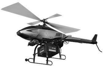
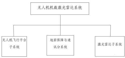
The invention relates to an unmanned aerial vehicle-mounted laser radar system, which consists of an unmanned aerial vehicle flying platform subsystem, a laser radar subsystem and ground protection and communication subsystems, wherein the unmanned aerial vehicle flying platform subsystem takes an unmanned helicopter as a carrying platform, the laser radar subsystem is used for acquiring three-dimensional spatial information and digital image data and consists of a laser scanner, an IMU (Inertial Measurement Unit), and a high-resolution aerially-photographing digital camera, and the ground protection and communication subsystems are used for protecting flying safety and timely returning working state information of the system. With the adoption of the unmanned aerial vehicle-mounted laser radar system, the patrol efficiency can be increased, the patrolling means is scientific, intuitive and accurate, the potential problems can be timely discovered so as to ensure safe operation and reduce economic losses, and thus, the unmanned aerial vehicle-mounted laser radar system has the characteristics of low cost, simplicity for operating, high accuracy of data and the like.
Description
technical field [0001] The invention relates to an unmanned aerial vehicle airborne laser radar system, which belongs to the field of laser radar remote sensing surveying and mapping. Background technique [0002] At present, there are more than 200 airborne lidar systems in the world, which are mostly used in urban planning, land management, power line design, highway, railway design, forestry, water conservancy, restoration of cultural relics and relics, and digital cities and other related fields. play an increasingly pronounced role. [0003] Most of the imported airborne lidar systems currently on the market are a complete system of organic combination, including laser scanners, digital cameras, inertial gyroscopes, control terminals, GPS, power supplies, etc., with large volume and weight of 100 more than kilograms. This kind of airborne laser radar system can only use small engine aircraft, such as Yun-5 aircraft, manned helicopters or other small aircraft, etc., us...
Claims
Login to View More Application Information
Patent Timeline
 IPC IPC(8): B64D47/00B64D47/08
Inventor 不公告发明人
Owner MIANYANG SKYEYE LASER TECH