Disc-taking machine

A technology for taking out the disk machine and the driving pulley, which is applied in the direction of conveyor objects, transportation and packaging, etc., to achieve the effect of convenient disassembly, convenient transportation, and guaranteed stability

Active Publication Date: 2012-03-21
WUHAN RENTIAN PACKAGING TECH
View PDF7 Cites 19 Cited by
  • Summary
  • Abstract
  • Description
  • Claims
  • Application Information

AI Technical Summary

Problems solved by technology

Obviously, the pallet picking equipment in the original palletizing production line can no longer meet the needs of the

Method used


Image

  • Disc-taking machine
  • Disc-taking machine
  • Disc-taking machine

Examples


Embodiment Construction

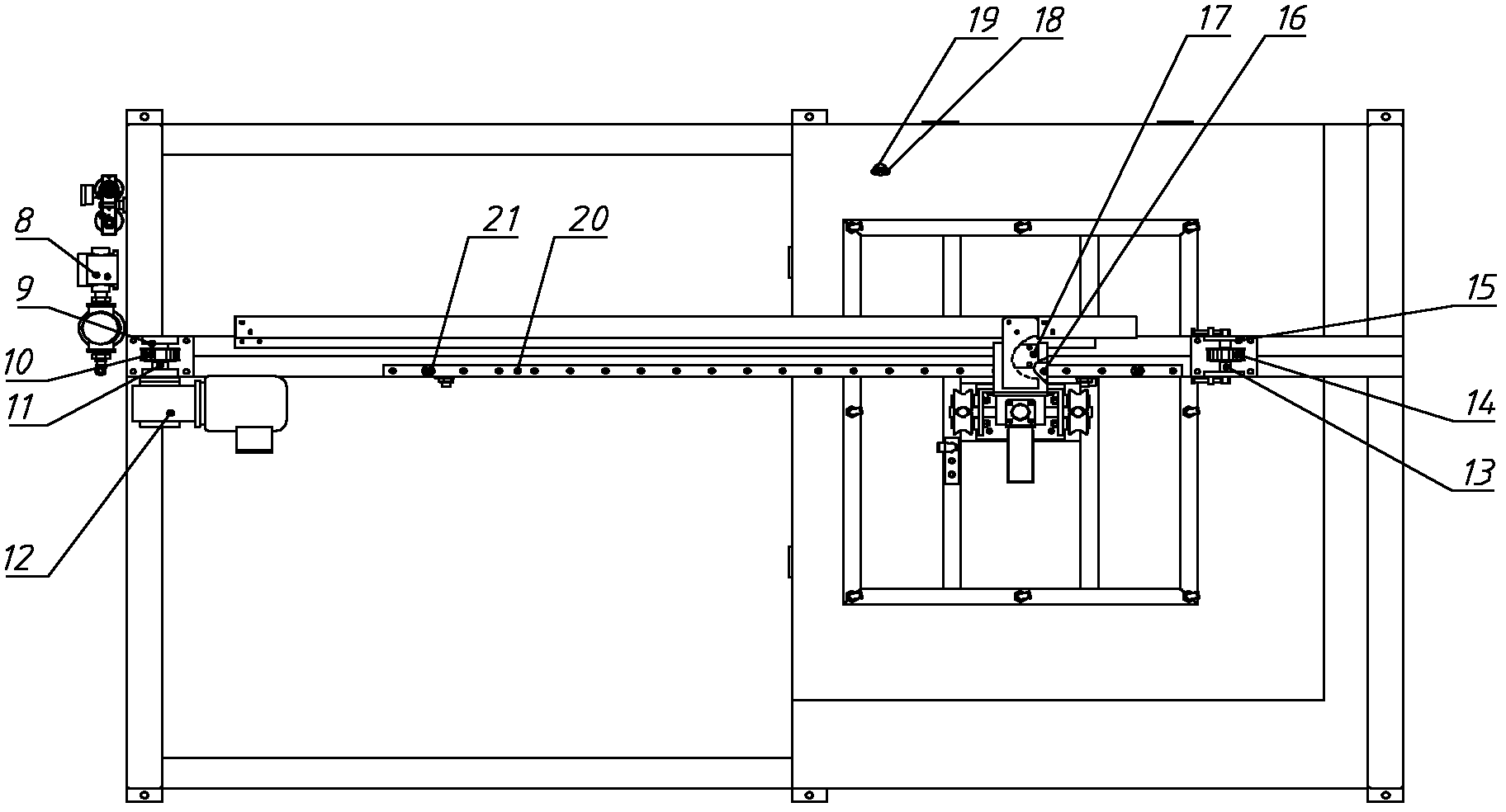
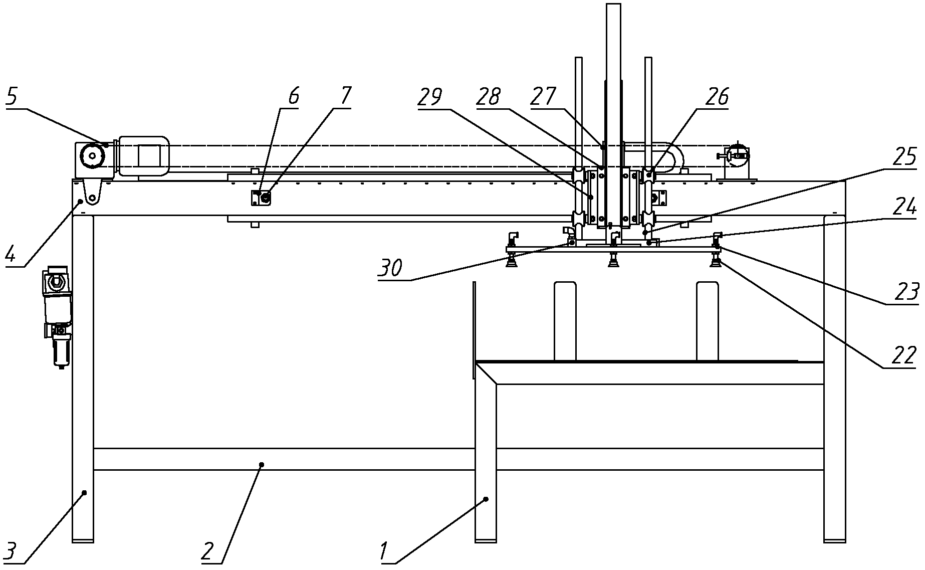
[0013] The present invention is described in detail below in conjunction with accompanying drawing:

[0014] Such as figure 1 , 2 As shown, the present invention mainly includes warehouse rack 1, cross brace 2, vertical beam 3, beam 4, synchronous belt 5, 2 pieces of start-stop sensor board 6, 2 pieces of inductive sensor 7, vacuum generator 8, driving pulley seat 9. Driving shaft 10, driving pulley 11, geared motor 12, pulley driven shaft 13, driven pulley 14, driven pulley seat 15, 2 pieces of slider 16, toothed cover 17, sensor bracket at the bottom of the library 18. Diffuse reflection sensor 19, two slide rails 20, four anti-collision blocks 21, suction cup 22, suction cup frame 23, connecting rod plate 24, two guide rods 25, eight rollers 26, bag taking cylinder 27, vertical seat 28. Two pieces of angle steel 29, gas distribution pipe 30, the cross brace 2 connects the storage rack 1 and the vertical beam 3 at the lower end, the cross beam 4 connects the storage rack 1...


PUM


Abstract

The invention relates to a disc-taking machine. The structure is that: a cross brace, a storehouse frame, a vertical beam and a transverse beam are connected into a frame; a vacuum generator is fixed on one side of the vertical beam; two sliding rails are fixed on the upper side and the lower side of the transverse beam; a drive pulley base, a drive shaft, a drive pulley, a speed-reducing motor, a pulley driven shaft, a driven pulley and a driven pulley base are arranged on the transverse beam; a toothed cover is fixed on one sliding block; a synchronous belt is sleeved on the drive pulley and the driven pulley and passes through the toothed cover; two sliding blocks are sleeved on the two sliding rails respectively; a vertical base is fixed on the two sliding blocks; a bag-taking cylinder is fixed on the vertical base and is connected with a connecting rod plate; two angle steels are fixed on two sides of the vertical base respectively; four roller wheels are fixed on each angle steel; guide rods pass through the middle parts of the roller wheels; one connecting rod plate is connected with the lower ends of two guide rods; the connecting rod plate is connected with a sucking discframe; a gas-distributing pipe and a sucking disc are arranged above the sucking disc frame; and the vacuum generator is connected with the sucking disc through the gas-distributing pipe. The invention adopts double sliding rails to guarantee the stability of disc-taking motion and prevent discs from falling off in the disc sucking process.

Description

technical field [0001] The invention belongs to the field of packaging machinery, and in particular relates to a tray removal machine for removing a new type of paper sliding tray or plastic sliding tray. Background technique [0002] At present, after packing and bagging granular or powdery materials in industries such as salt and chemical industry, palletizing is generally required for convenient storage and transportation, which involves pallets. Traditional forms of pallets include wooden pallets, stainless steel pallets, plastic pallets, etc., but sometimes because of high cost or inapplicability, some use new paper sliding pallets or plastic sliding pallets. Obviously, the tray-taking equipment in the original palletizing production line can no longer meet the needs of the market, so there is an urgent need for a tray-taking machine corresponding to a new type of paper slip tray or plastic slip tray. Contents of the invention [0003] The purpose of the present inve...

Claims


Application Information

Patent Timeline
IPC IPC(8): B65G47/04B65G47/91
Inventor 李浩王军伟程亮李怀刚
Owner WUHAN RENTIAN PACKAGING TECH
Why Eureka
Try Eureka