Chain tensioner device

A chain tensioning device, chain technology, applied in the direction of transmission, belt/chain/gear, mechanical equipment, etc.

Active Publication Date: 2012-03-21
HONDA MOTOR CO LTD
View PDF3 Cites 2 Cited by
  • Summary
  • Abstract
  • Description
  • Claims
  • Application Information

AI Technical Summary

Problems solved by technology

[0005] However, in the above-mentioned chain tensioner, it is desired to keep the load with which the main arm presses the endless chain constant even when the endless chain is stretched. It is long and elongated, and as a result, there is a problem that the load that the main arm presses against the endless chain gradually decreases as the endless chain elongates.

Method used


Image

  • Chain tensioner device
  • Chain tensioner device
  • Chain tensioner device

Examples


no. 1 approach

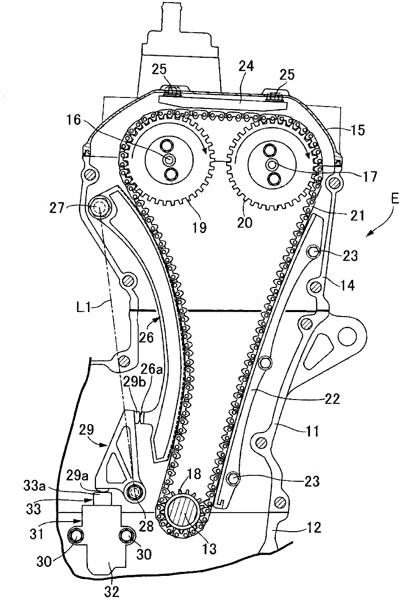
[0038] like figure 1 As shown, a crankshaft 13 is rotatably supported between a cylinder block 11 of the engine E and a crankcase 12 coupled to the lower surface of the cylinder block. In addition, an intake camshaft 16 and an exhaust camshaft are rotatably supported between the cylinder head 14 coupled to the upper surface of the cylinder block 11 and the cylinder head cover 15 coupled to the upper surface of the cylinder head 14. 17. On the driving sprocket 18 provided at the shaft end of the crankshaft 13 and the two driven sprockets 19 and 20 respectively provided at the shaft ends of the intake camshaft 16 and the exhaust camshaft 17, a chain consisting of an endless chain is wound. The timing chain 21 , the intake camshaft 16 and the exhaust camshaft 17 are driven at one-half the rotational speed of the crankshaft 13 .

[0039] The first fixed chain guide 22 is in sliding contact with the chord of the tight side of the timing chain 21 between the drive sprocket 18 and ...


PUM


Abstract

The invention provides a chain tensioner device, which can maintain load of an annular chain even the annular chain extends and is pressed by a main arm connected by an assistant arm and a plunger of a tensioning lifter. When the anuular chain (21) reaches a maximal extension amount, at contact parts (33a, 29a) of the plunger (33) and the assistant arm (29), the movement direction (A1) of the plunger is perpendicularly crossed with a tangent line (T1) of the contact parts (33a, 29a), therefore transmission efficency of the load (F1) of the plunger then toward the assistant arm (29) reaches the maximum, when the extension amount of the anuular chain does not reach the maximum, the transmission efficency of the load of the plunger toward the assistant arm becomes lower. Therefore, via the increase of the transmission efficiency, amount of the load of the plunger reducing with increase of the extension amount of the annular chain and spring extension of the tension lifter is complemented, therefore, the main arm (26) is made to press the annular chain with a roughly-fixed load regardless of extension amount of the annular chain.

Description

technical field [0001] The present invention relates to a chain tensioner that transmits the force of a plunger tensioning a lifter via a secondary arm to a main arm connected to an endless chain wound between a drive sprocket and a driven sprocket sliding contact. Background technique [0002] Such a chain tensioner is known from Patent Document 1 below. [0003] According to this chain tensioner, by setting the lever ratio of the auxiliary arm to a large value, not only can the main arm be pressed against the endless chain with a moderate load while using a spring with a large spring constant, but also the Even when the endless chain is elongated due to wear or the like, the amount of elongation of the spring can be reduced to minimize fluctuations in the load with which the main arm presses the endless chain. [0004] Patent Document 1: Japanese Publication No. 60-86665 [0005] However, in the above-mentioned chain tensioner, it is desired to keep the load with which ...

Claims


Application Information

Patent Timeline
Patent Type & Authority Applications(China)
IPC IPC(8): F16H7/08
Inventor 小岩洋二郎山田真嗣关雅夫若林智弘
Owner HONDA MOTOR CO LTD
Why Eureka
Try Eureka