
Method and system for testing novel contra-rotating dual-rotor motor driver

A dual-rotor motor and testing system technology, applied to instruments, measuring electronics, measuring devices, etc., can solve problems such as differences in test results, inability to record data in real time, blank test equipment, etc., and achieve accurate and effective characteristic testing, which is conducive to accurate testing , The effect of facilitating human-computer interaction

Active Publication Date: 2012-03-21
KUNSHAN HANHUI ELECTRONICS TECH CO LTD
View PDF4 Cites 20 Cited by
  • Summary
  • Abstract
  • Description
  • Claims
  • Application Information

AI Technical Summary

Problems solved by technology

However, the detection equipment for the special drive system of electric vehicles is still blank, especially for the new dual-rotor drive axle lack of a general detection platform
Even a small number of existing testing equipment for new dual-rotor drive axles are modified from original engine testing equipment. These testing equipment for new dual-rotor drive axles are generally prone to deviations, resulting in relatively poor test results. The big difference: the inspection function is single and incomplete, cannot record data in real time, automatically forms status line diagrams and charts, and also contains some useless detection items
Therefore, these existing testing equipment for the new dual-rotor drive axle can only detect certain performance parameters, and the results obtained cannot fully measure the performance and operating status of the motor, and the detection accuracy needs to be improved, which is not conducive to the development of new electric vehicles. Drive System Research

Method used


Image

  • Method and system for testing novel contra-rotating dual-rotor motor driver
  • Method and system for testing novel contra-rotating dual-rotor motor driver

Examples


Embodiment Construction

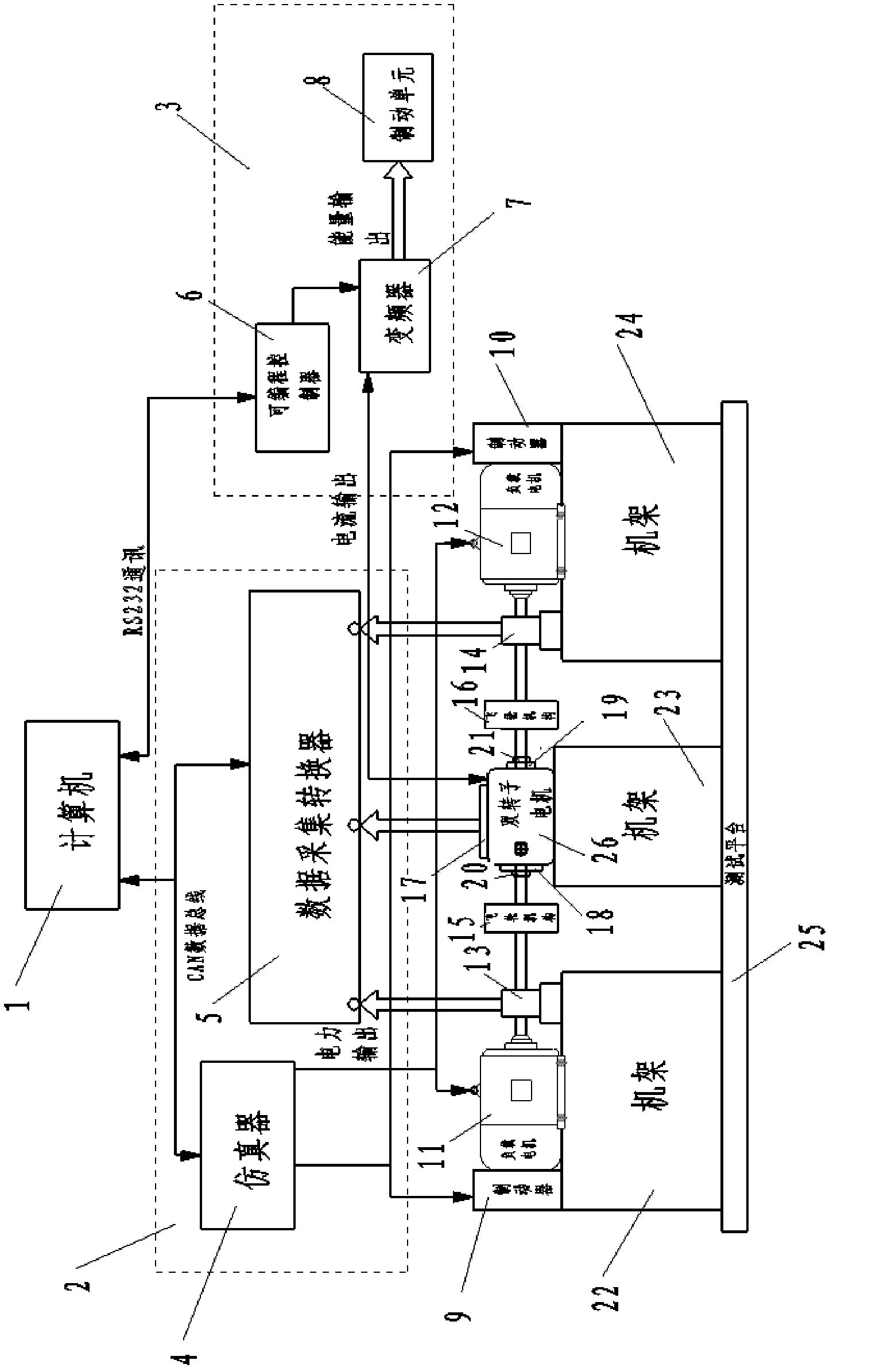
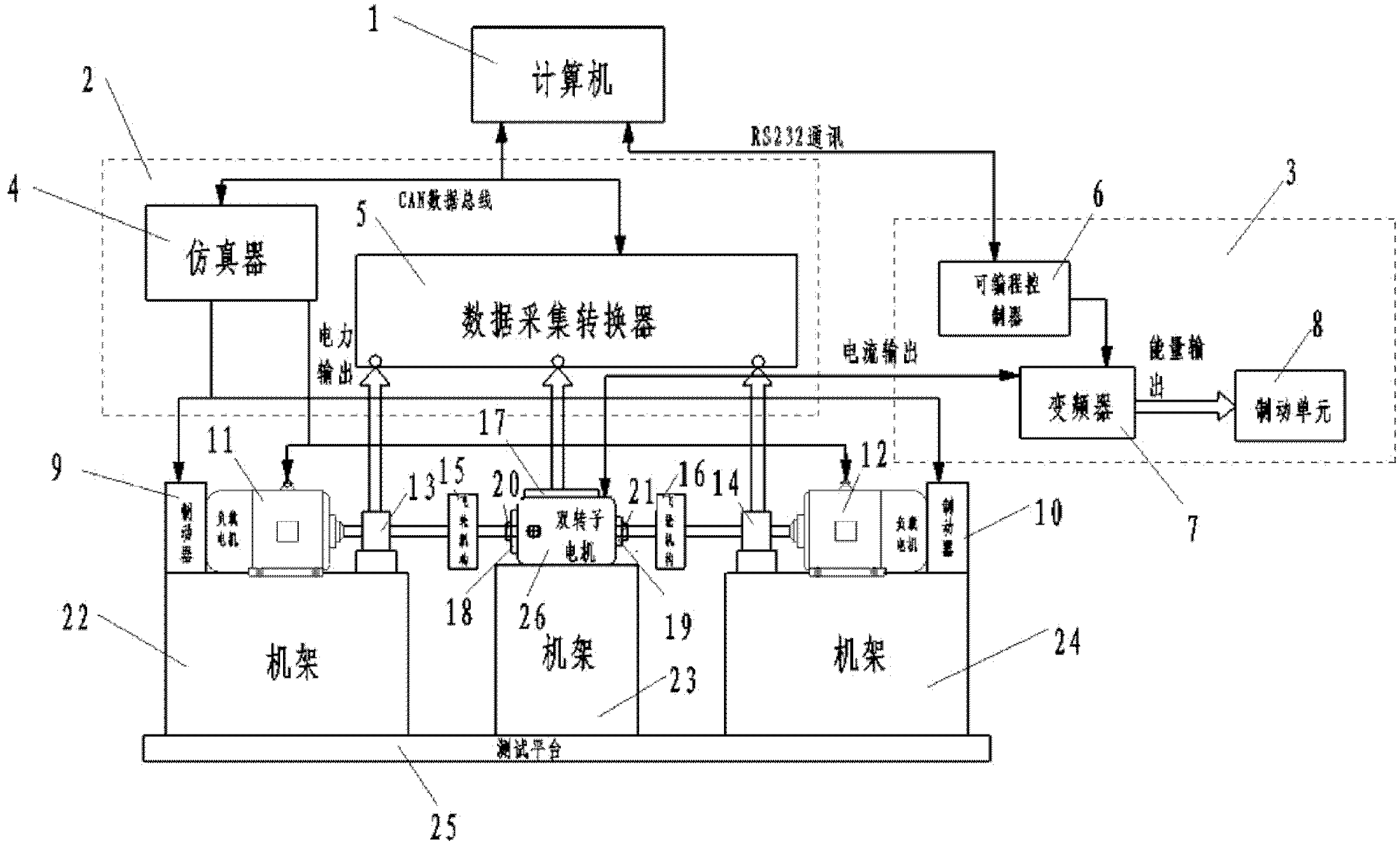
[0036] A test system of the present invention aimed at testing a new type of electric vehicle drive system-a counter-rotating double-rotor motor driver is closely combined with a bench mechanism part and a control part.

[0037] The platform mechanism part includes a counter-rotating double-rotor motor 26, left and right deceleration (reversing) mechanisms 18, 19, left and right universal transmission mechanisms 20, 21, supporting and fixing devices, testing devices, working condition parameter detection sensor groups 5, and left and right brakes 9 , 10. The double-rotor motor 26 is composed of an outer rotor and an inner rotor with winding windings. The outer rotor is connected to the test device and the brake 10 on one side through the reduction mechanism 19 and the universal transmission mechanism 21 on one side; the inner rotor passes through the other side in turn. The deceleration and reversing mechanism 18 and the universal transmission mechanism 20 are connected with t...


PUM


Abstract

The invention discloses a system for testing a novel contra-rotating dual-rotor motor driver. The system comprises a rack mechanism part and a control part, wherein the rack mechanism part comprise a contra-rotating dual-rotor motor, a left retarding (reversing) mechanism, a right retarding (reversing) mechanism, a left universal transmission mechanism, a right universal transmission mechanism, asupporting fixing device, a test device, a working condition parameter detection sensor group, a left brake and a right brake. The invention has the beneficial effect that the system for testing a novel contra-rotating dual-rotor motor driver can be used for replacing mass inertia with rotational inertia by regulating a flywheel mechanism according to the practical situations of different vehicles, and therefore, the practical state of the dual-rotor driving system when the dual-rotor driving system is installed on a vehicle can be realized.

Description

technical field [0001] The present invention relates to a test system and a test method in the field of motor drive and power generation, in particular to a system and test method for counter-rotating dual-rotor motor drivers that can be widely used in the fields of electric vehicle drive, new energy power generation, variable speed transmission, etc. its test method. Background technique [0002] Due to the environmental protection requirements and restrictions on energy and environmental issues, people have higher and higher requirements for automobile energy saving and new energy power generation. In particular, electric vehicles are a major trend in the development of automobiles to replace traditional internal combustion engine vehicles. [0003] Taking an electric vehicle as an example, the drive system is the source of power and the heart of an electric vehicle, so the research on the drive system of an electric vehicle is particularly important. However, the detecti...

Claims


Application Information

Patent Timeline
Patent Type & Authority Applications(China)
IPC IPC(8): G01D21/02G01R31/00
Inventor 周斯加杨勇夏景演龙江启
Owner KUNSHAN HANHUI ELECTRONICS TECH CO LTD
Learn More