

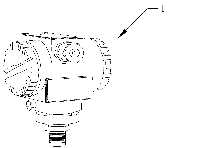
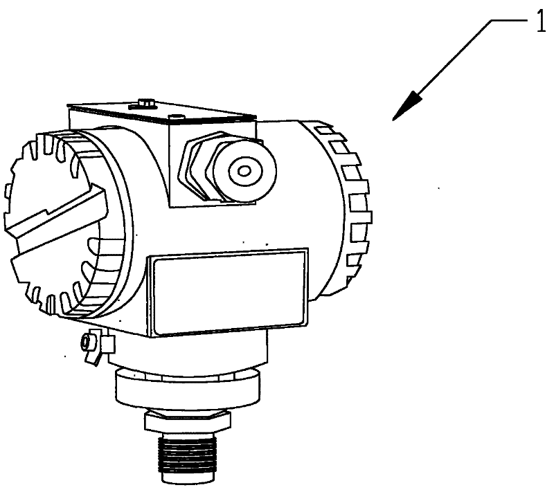
Pressure transmitter
A transmitter and pressure sensor technology, applied in the measurement of fluid pressure, instruments, fluid pressure measurement using capacitance changes, etc., can solve the problems of unable to adjust the range, unable to adjust the range
- Summary
- Abstract
- Description
- Claims
- Application Information
AI Technical Summary
Problems solved by technology
Method used
Image

Examples
Embodiment Construction
[0009] The present invention will be described in further detail below in combination with specific embodiments.
[0010] The working principle of the pressure transmitter is: the two pressures of the measured medium are passed into the high and low pressure chambers, and act on the isolation diaphragms on both sides of the delta element (that is, the sensitive element), through the isolation sheet and the filling in the element. The liquid is sent to both sides of the measuring diaphragm. The measuring diaphragm and the electrodes on the insulating sheets on both sides form a capacitor respectively. When the pressure on both sides is not consistent, the measuring diaphragm will be displaced, and the displacement is proportional to the pressure difference, so the capacitance on both sides is not equal. Through the oscillation and demodulation link, it is converted into a signal proportional to the pressure. The working principle of pressure transmitter and absolute pressure t...
PUM
 Abstract
Description
Claims
Application Information