
Twisting machine

A twisting machine and frame technology, applied in the field of cable or cable processing equipment, twisting machine, can solve the problems of unstable tension, cable damage, low work efficiency, etc., to achieve good transmission stability and quality assurance Reliability and the effect of improving processing efficiency

Active Publication Date: 2012-03-21
ZHEJIANG SHIP ELECTRONICS TECH
View PDF4 Cites 7 Cited by
  • Summary
  • Abstract
  • Description
  • Claims
  • Application Information

AI Technical Summary

Problems solved by technology

[0002] Power cables and communication cables are the second pillar products of my country's export products. A large cable is twisted by multiple or pairs of small cables at a certain helical distance to improve the bending resistance of the cable and improve the electronic performance. The anti-interference ability of the signal, so the machine used for twisting is applied. The biggest disadvantage of the existing twisting machine is that it can only achieve three times the maximum twist when twisting, so the work efficiency is relatively low. Moreover, the tension is not stable during processing, and the stability is poor, which is easy to cause damage to the cable during processing. In addition, when twisting two different wires, the processed cables cannot be used due to different forces.

Method used


Image

  • Twisting machine
  • Twisting machine
  • Twisting machine

Examples


Embodiment Construction

[0025] The following are specific embodiments of the present invention and in conjunction with the accompanying drawings, the technical solutions of the present invention are further described, but the present invention is not limited to these embodiments.

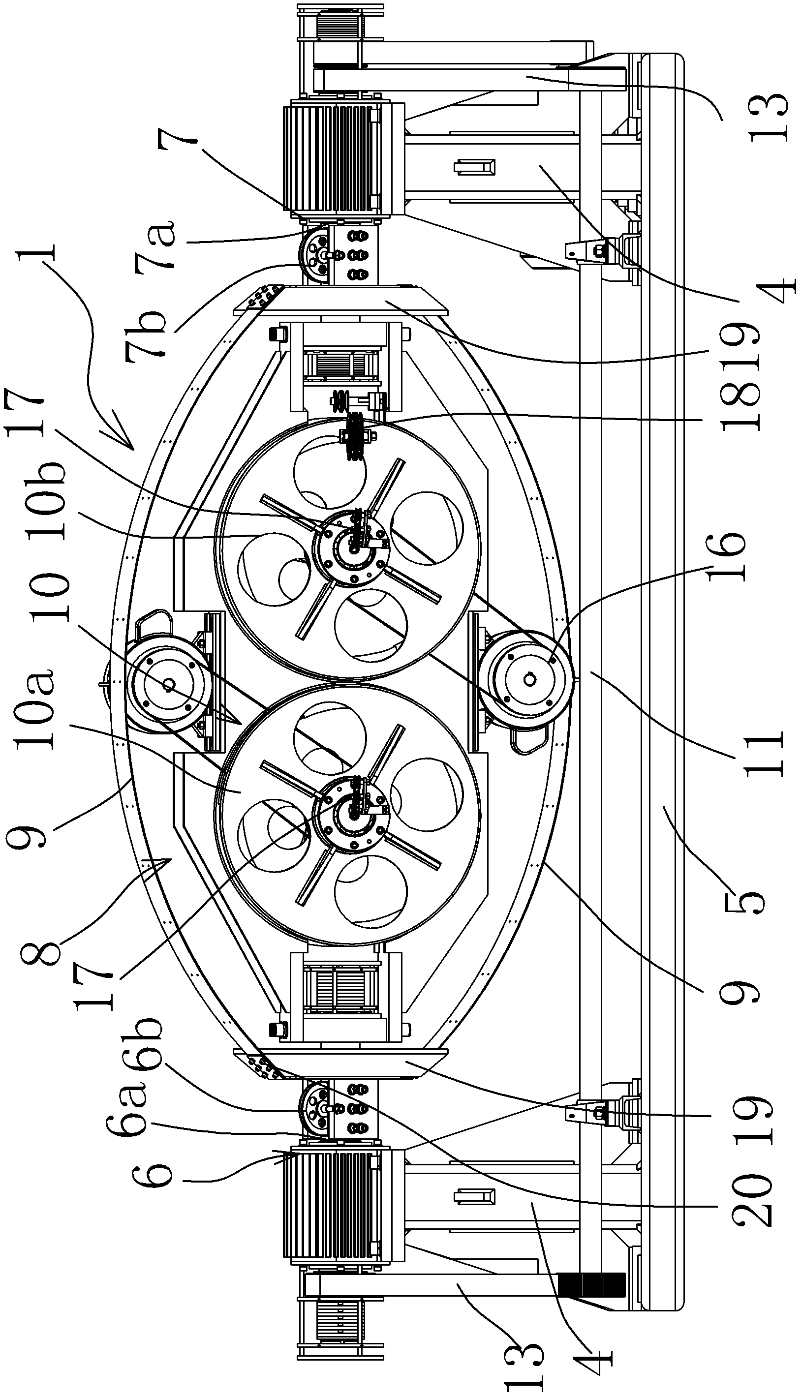
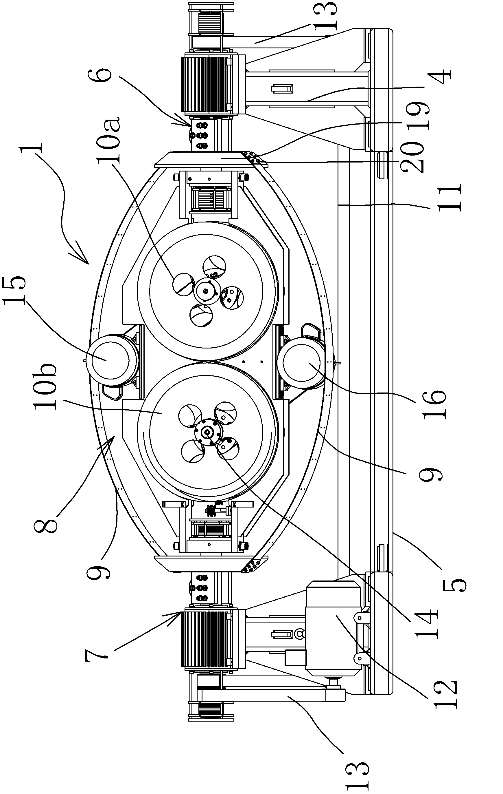
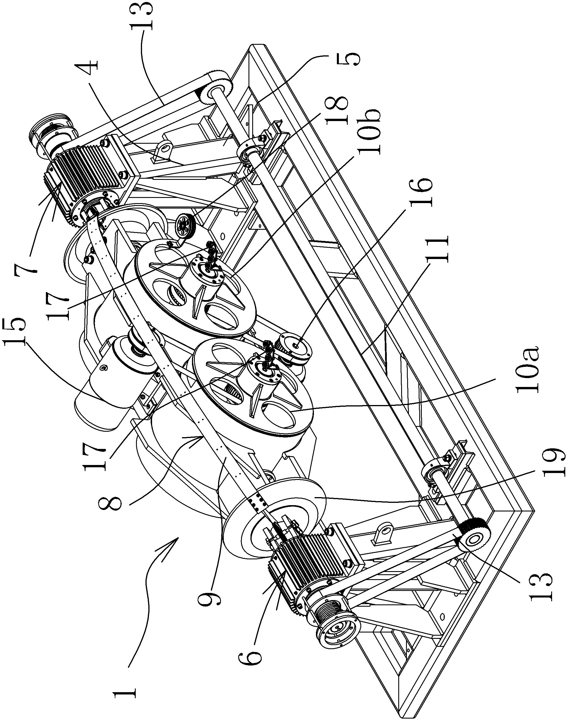
[0026] In the figure, the pay-off mechanism 1; the take-up mechanism 2; the lifting part 3; the frame 4; the base 5; the front main shaft part 6; the front main shaft 6a; the front guide wheel 6b; the rear main shaft part 7; the rear main shaft 7a; the rear guide wheel 7b; first cradle assembly 8; twisted bow 9; pay-off reel 10; first pay-off reel 10a; second pay-off reel 10b; synchronous shaft 11; transmission motor 12; Motor 15; second pay-off motor 16; outgoing line traction wheel 17; guide wheel 18; twisted pair disc 19; pressing sheet 20; incoming line main shaft part 21; incoming line main shaft 21a; incoming line guide wheel 21b; outgoing line main shaft part 22 Outlet main shaft 22a; Outlet guide wheel 22b; Second ...


PUM


Abstract

The invention belongs to the technical field of machinery and provides a twisting machine. The twisting machine comprises a pay-off mechanism, a take-up mechanism and a traction mechanism, wherein the take-up mechanism also comprises a stander and a machine seat; the stander is arranged on the machine seat; a wire inlet main shaft part and a wire outlet main shaft part are arranged on the left side and the right side of the stander respectively; a second cradle component is arranged between the wire inlet main shaft part and the wire outlet main shaft part; the second cradle component comprises a twisting arch, a wire spool and a wire discharging part; a twisted cable led out by the pay-off mechanism is further twisted into a twisted cable which has a four-time twist pitch through the twisting arch in the second cradle component; and the further twisted cable on the wire arranging part is conveyed and tidily distributed on the wire spool. The twisting machine has the advantages that: the twisted cable can be further twisted into the twisted cable which has the four-time twist pitch, so the processing working efficiency is improved; as the parts are coordinated with one another to drag the cable, so the transmission stability is high; and the cable cannot be damaged during processing, so the quality reliability of a processed product is guaranteed.

Description

technical field [0001] The invention belongs to the technical field of machinery, and relates to equipment for processing cables or cables, in particular to a twisting machine. Background technique [0002] Power cables and communication cables are the second pillar products of my country's export products. A large cable is twisted by multiple or pairs of small cables at a certain helical distance to improve the bending resistance of the cable and improve the electronic performance. The anti-interference ability of the signal, so the machine used for twisting is applied. The biggest disadvantage of the existing twisting machine is that it can only achieve three times the maximum twist when twisting, so the work efficiency is relatively low. Moreover, the tension is not stable during the processing, and the stability is poor, which is easy to cause damage to the cable during the processing. In addition, when two different wires are twisted, the processed cables cannot be used d...

Claims


Application Information

Patent Timeline
Patent Type & Authority Applications(China)
IPC IPC(8): H01B13/02
CPCD07B3/10D07B2207/207
Inventor 白建国李鹏陈静王国强竺永宏朱江南
Owner ZHEJIANG SHIP ELECTRONICS TECH
Learn More