Silicon microphone and packaging structure of product applying same

A technology of silicon microphone and packaging structure, which is applied in the direction of sensors, electrostatic transducers, microphones, electrical components, etc., can solve the problems of MEMS chip work interference and affect the sound pickup effect of silicon microphones, and achieve the effect of noise reduction

Active Publication Date: 2012-03-21
GOERTEK MICROELECTRONICS CO LTD
View PDF6 Cites 14 Cited by
  • Summary
  • Abstract
  • Description
  • Claims
  • Application Information

AI Technical Summary

Problems solved by technology

[0004] However, since the working principle of the silicon microphone requires that its structure must have a sound hole connected to the external space, this makes it easy for external light to irradiate into the silicon microphone through the sound hole 51 of the mobile phone, the sound hole 61 of the rubber sleeve and the sound hole 21 of the silicon microphone. Inside, and irradiate on the MEMS chip, this will bring some interference to the work of the MEMS chip, commonly known as "light noise"
Moreover, in order to ensure the transmission of sound signals and the need to ensure the acoustic performance, the sound hole 51 of the mobile phone, the sound hole 61 of the rubber sleeve and the sound hole 21 of the silicon microphone cannot be designed too small, otherwise the sound pickup effect of the silicon microphone will be affected

Method used


Image

  • Silicon microphone and packaging structure of product applying same
  • Silicon microphone and packaging structure of product applying same
  • Silicon microphone and packaging structure of product applying same

Examples


Embodiment 1

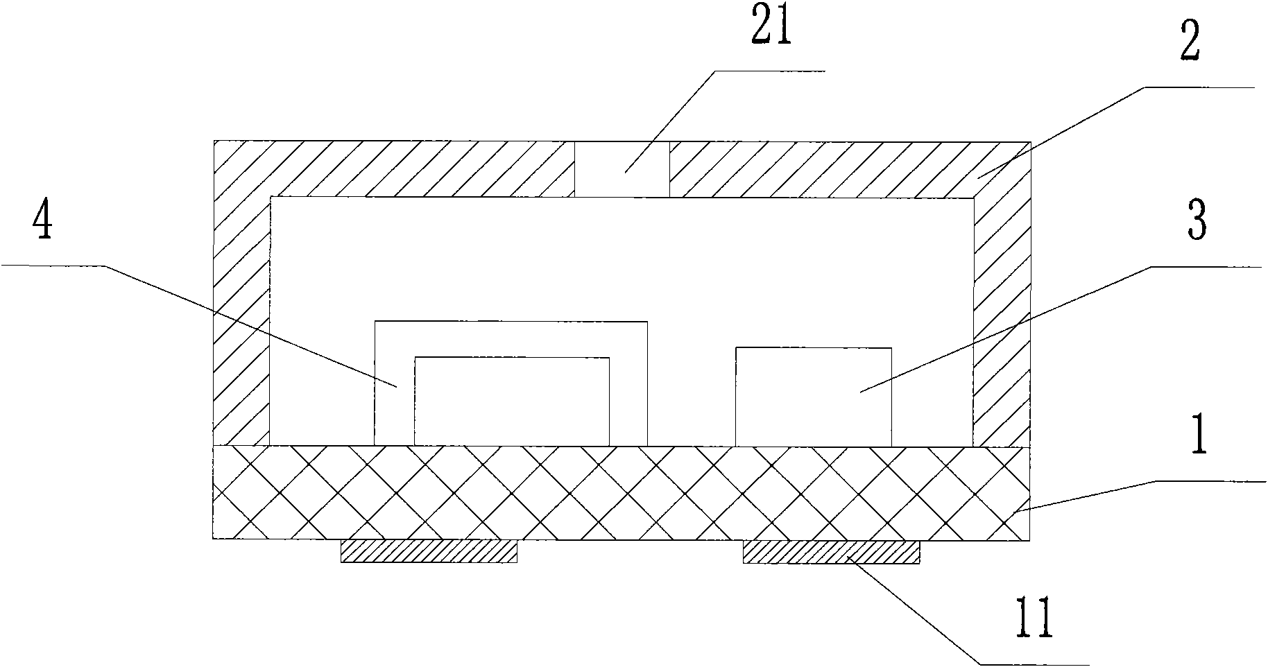
[0030] image 3 with Figure 4 It is a schematic cross-sectional structure diagram and a plan view of Embodiment 1 of the present invention. Such as image 3 , Figure 4 As shown, in Embodiment 1, a square circuit board 1 and a square metal shell 2 constitute the external package of the silicon microphone, and the metal shell 2 is provided with a sound hole 21 for receiving external sound signals, and the circuit board inside the package 1, IC chip 3 and MEMS chip 4 are installed respectively, wherein MEMS chip 4 is made by utilizing MEMS (micro-electro-mechanical system) technology, and can convert external sound signals into electrical signals, and the electrodes of MEMS chip 4 and circuit board 1 The IC chip 3 is electrically connected, and finally the electrical signal processed by the IC chip is transmitted to the outside of the silicon microphone through a plurality of pads 11 provided on the outer surface of the circuit board 1 and connected to the external circuit. ...

Embodiment 2

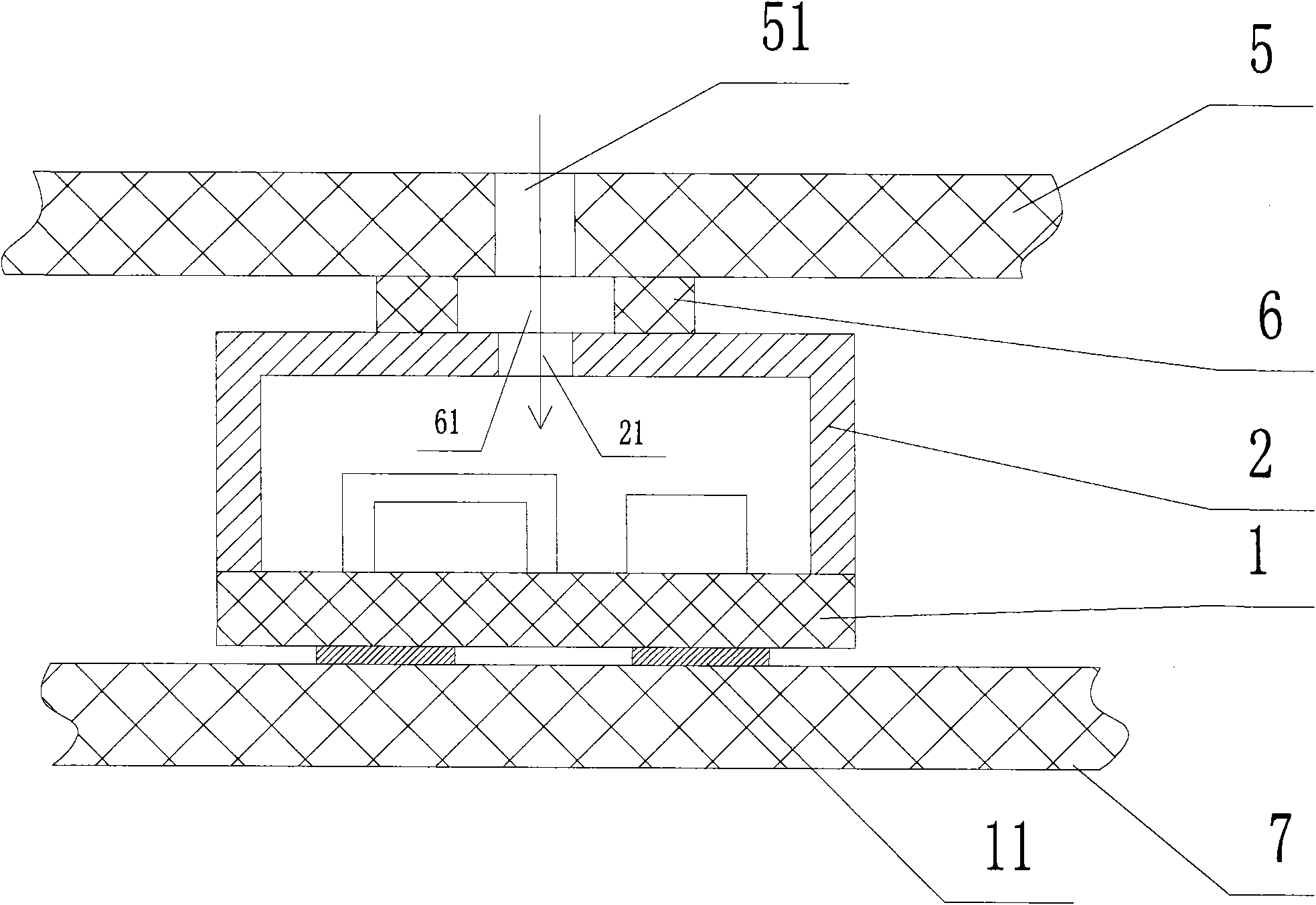
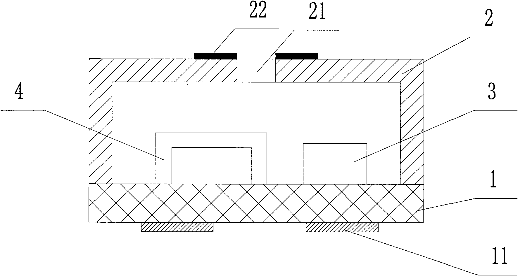
[0039] Image 6 with Figure 7 They are a schematic cross-sectional structure diagram and a top view of Embodiment 2 of the present invention, respectively. Such as Image 6 , Figure 7 As shown, in the second embodiment, a square circuit board 1 and a square metal shell 2 constitute the external package of the silicon microphone, and the metal shell 2 is provided with a sound hole 21 for receiving external sound signals, and the circuit inside the package On board 1, IC chip 3 and MEMS chip 4 are installed respectively, wherein MEMS chip 4 is to utilize MEMS (micro-electro-mechanical system) technology to make, can convert external sound signal into electric signal, the electrode of MEMS chip 4 and circuit board 1 The IC chip 3 on the circuit board 1 is electrically connected, and finally the electrical signal processed by the IC chip is transmitted to the outside of the silicon microphone through a plurality of pads 11 provided on the outer surface of the circuit board 1 ...

Embodiment 3

[0044] Figure 8 with Figure 9 It is a schematic cross-sectional structure diagram and a bottom view of Embodiment 3 of the present invention, respectively.

[0045] Such as Figure 8 with Figure 9 As shown, similar to the previous embodiment, the silicon microphone of the third embodiment also consists of a square circuit board 1 and a square metal casing 2 to form an external package, and IC chips 3 are respectively installed on the circuit board 1 inside the package. And MEMS chip 4, wherein MEMS chip 4 is to utilize MEMS (micro-electromechanical system) technology to make, can convert the external sound signal into electric signal, the electrode of MEMS chip 4 is electrically connected with IC chip 3 on the circuit board 1, and finally The electrical signal processed by the IC chip is transmitted to the outside of the silicon microphone through a plurality of pads 11 provided on the outer surface of the circuit board 1 and connected to an external circuit.

[0046] D...


PUM


Abstract

The invention provides a silicon microphone and a packaging structure of a product applying same, wherein the silicon microphone comprises a shell and a circuit board which form the external packaging structure of the silicon microphone, an MEMS (Micro-electromechanical Systems) chip is arranged on the surface of the circuit board inside the packaging structure, sound holes used for receiving external sound signals are arranged in the packaging structure, and the surface of the external periphery of the sound holes is provided with a deep-color coating. The invention can realize good light and noise reducing effects only by a manner that the deep-color coating is arranged around the sound holes in the external surface of the silicon microphone, is simple to design and easy to realize, can not increase the production cost and the size of products, and can not affect the picking-up effect of the product.

Description

technical field [0001] The present invention relates to the technical field of electroacoustic converters, and more specifically, relates to a silicon microphone capable of preventing light noise and a package structure of its application products. Background technique [0002] With the progress of society and the development of technology, in recent years, as the volume of electronic products such as mobile phones and notebook computers has been continuously reduced, people have higher and higher requirements for the performance of these portable electronic products, which also require matching electronic products. Parts continue to shrink in size, performance and consistency. In this context, many new products have been launched in the field of microphone products, one of the important parts of the above-mentioned portable electronic products, among which silicon microphones realized in batches using semiconductor manufacturing and processing technology are representative ...

Claims


Application Information

Patent Timeline
Patent Type & Authority Applications(China)
IPC IPC(8): H04R19/04H04R31/00
Inventor 宋青林
Owner GOERTEK MICROELECTRONICS CO LTD
Why Eureka
Try Eureka